
Ducati Diavel Service Manual: Exhaust system
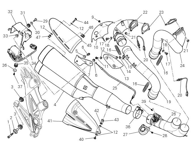
- Screw
- Bush
- Vibration damper mount
- Silencer
- Washer
- Screw
- Bracket
- Nut
- Nut
- Upper heat guard
- Screw
- Washer
- Central heat guard
- Spacer
- Clip nut
- Long exhaust spring
- Plug
- Sealing washer, thickness 1
- Vertical exhaust pipe
- Lambda sensor
- Nut
- Vertical flange
- Exhaust gasket
- Horizontal flange
- Flexible cable
- Central exhaust pipe
- Exhaust protection
- Screw
- Screw
- Washer
- Rubber pad
- Support
- Spacer
- Exhaust valve motor
- Rubber pad
- Washer
- Screw
- Clamp
- Circlip
- Screw
- Lower heat guard
- Spacer
- Quick-release fastener
- Screw
- Upper heat guard
- Rubber mounting
- Spacer
Spare parts catalogue
Diavel abs exhaust system
Diavel carbon abs exhaust system
Important
Bold reference numbers in this section identify parts not shown in the figures alongside the text, but which can be found in the exploded view diagram.
- Removing the silencer
- Removal of the exhaust system
- Refitting the exhaust system
- Refitting the silencer
 Refitting the air filters
Apply universal sealant in the air duct (2) and (6) groove (d).
Fit seal (7) in the groove (d) having care to place it correctly in the relevant
seat so as to avoid abnormal wrinkles.
Pull o ...
 Removing the silencer
Loosen the clamp (38) that retains the silencer (4) to the complete exhaust
system.
While holding the nut (8), loosen the screw (1) and remove the silencer (4)
from the motorcycle.
Loose ...
Other materials:
Digital rpm indication function
This function displays the number of rpms for improved accuracy when setting
idle rpm.
To access the function it is necessary to view the ""setting" menu", using
buttons (1) "s" or (2) "t" select the "rpm"
function and press the reset button (3) to confirm.
The display shows the numerical v ...
Changing the engine oil and filter cartridge
Note
This operation has to be carried out with hot engine (but turned off)
because the oil in these conditions is more fluid and
its evacuation is faster and complete.
Remove the drain plug (3) with seal (a) from the oil sump and allow the oil
to drain off.
Warning
Dispose of oil and/or fil ...
Programming/reprogramming keys
The dds diagnosis instrument is required in order to programme/reprogramme
the keys. The key programming procedure
is launched from this instrument.
To start the key programming/reprogramming procedure it is necessary to have at
least one of the keys that start the
vehicle available (i.E. I ...