
Ducati Diavel Service Manual: Refitting the cooling system hoses and unions
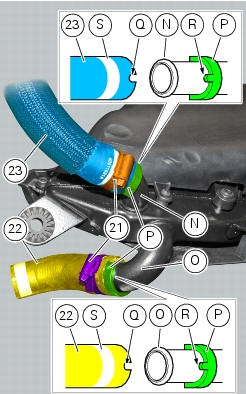
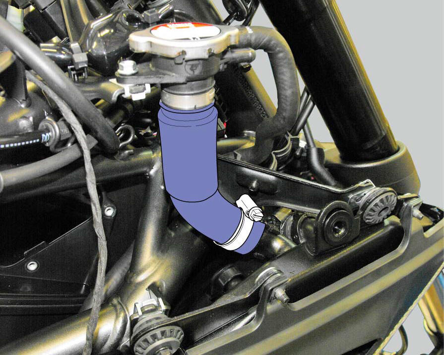
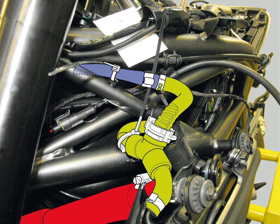
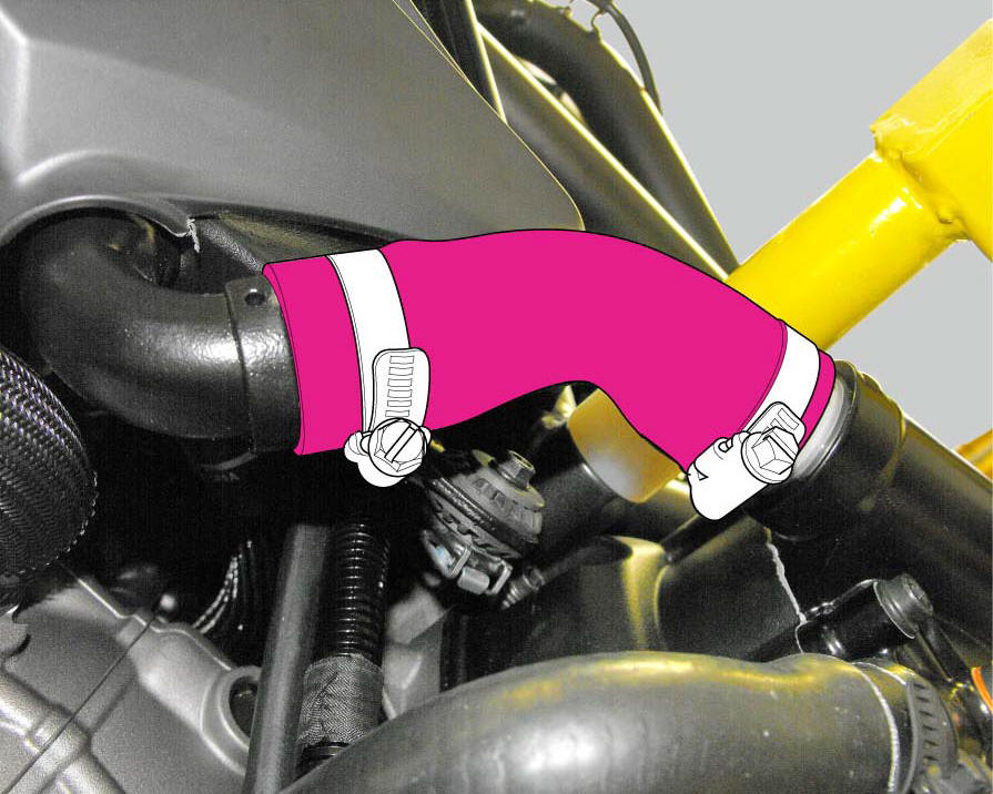
Position the pump/radiator sleeve (22) and the radiator/radiator sleeve (23).
Fit sleeve (23) and sleeve (22) to their corresponding fittings (n) and (o), and bring them fully home on collars (p).
Note
Sleeves (23) and (22) must be oriented so that the grooves (q) match the tabs (r) on fittings (n) and (o).
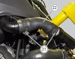
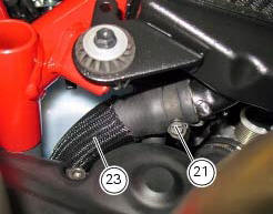
Insert the clip (21) on sleeve (23) and the clip (21) on sleeve (22), bringing them to the position of the white marks (s) on the sleeves.
Orient the clamps (21) as shown and tighten them to a torque of 2.5 Nm +/- 10% (sect. 3 - 3, Frame torque settings).
Tighten the clamps (21) to a torque of 2.5 Nm +/- 10% (sect. 3 - 3, Frame torque settings).
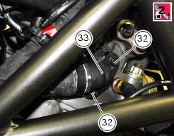
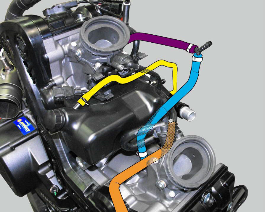
Install one gasket (31) into the seat of the vertical head fitting (33).
Fix the fitting (33) on the vertical head by means of the screws (32) with prescribed threadlocker, and tighten them to a torque of 6 nm (min. 5 Nm - max. 7 Nm) (sect. 3 - 3, Engine torque settings).
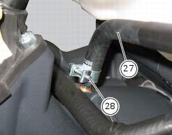
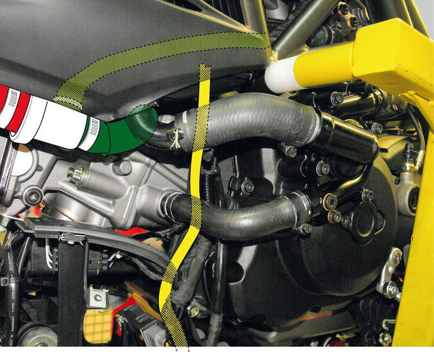
Place the breather pipe (27) on the half-casing fitting and tighten the clip (28).
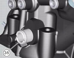
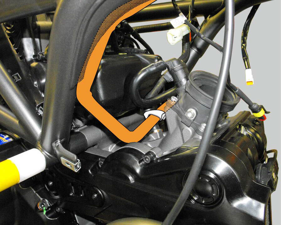
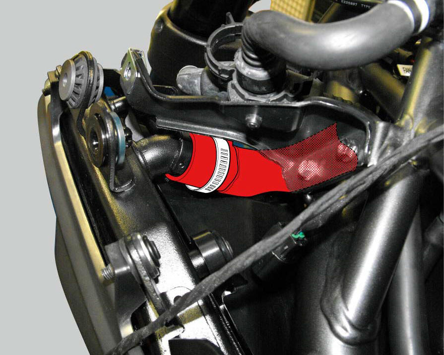
If removed, fit the coolant union (36) on the horizontal cylinder head and tighten it to a torque of 20 nm (min. 18 Nm - max. 22 Nm) (sect. 3 - 3, Frame torque settings).
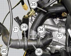
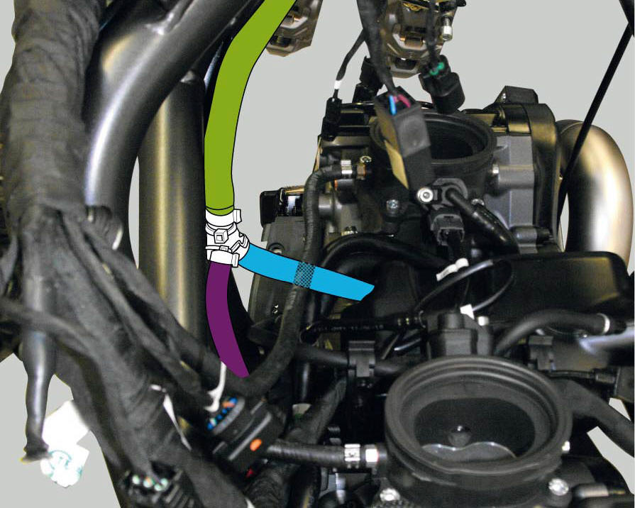
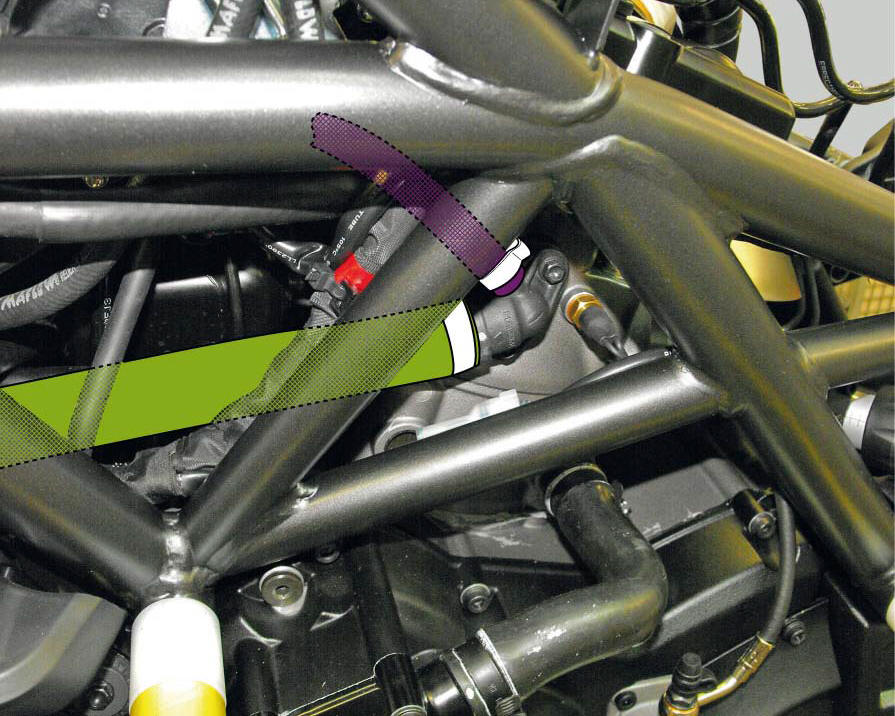
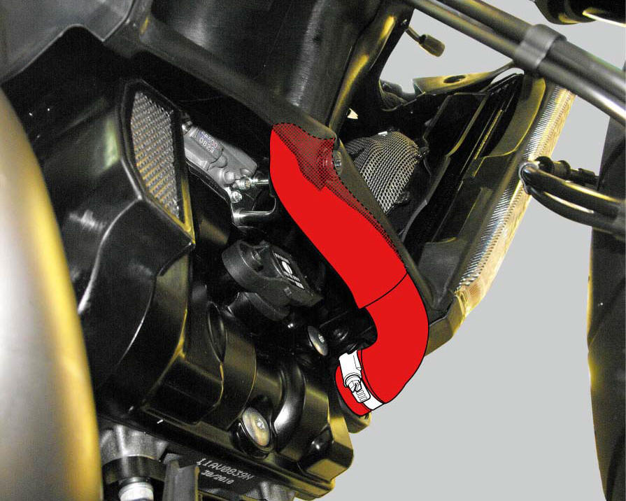
Assemble the thermostat (38) - thermostat/head sleeve (35) assembly by coupling and tightening them to a torque of 2.5 Nm +/- 10% (sect. 3 - 3, Frame torque settings) - and the thermostat/head sleeve (37) - radiator/thermostat sleeve (40) by tightening the clamps (21) and (34).
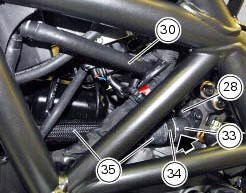
Place breather pipe (30) on the vertical head and tighten the clip (28) to a torque of 2.5 Nm +/- 10% (sect. 3 - 3, Frame torque settings).
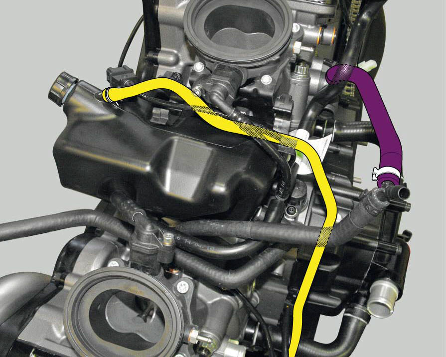
Fit the clamp (34) on the union (33) matching to dots.
Position the thermostat unit (38) - thermostat/head sleeve (35) - thermostat/head sleeve (37) with the clips (34) and tighten the clips (34) to a torque of 2.5 Nm +/- 10% (sec. 3 - 3, Frame torque settings).
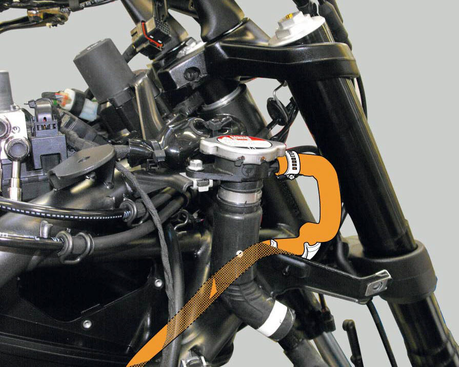
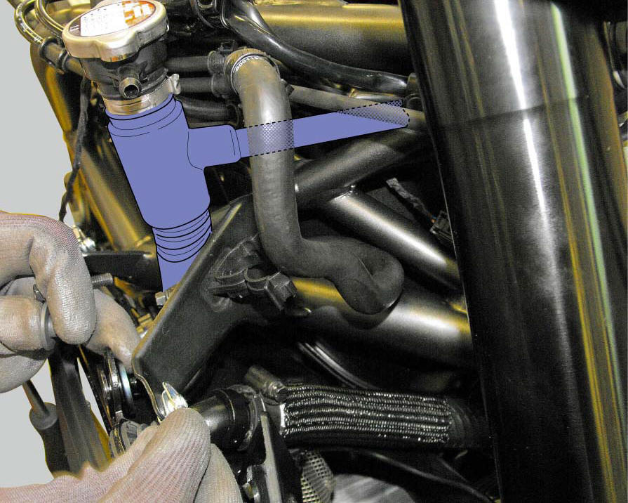
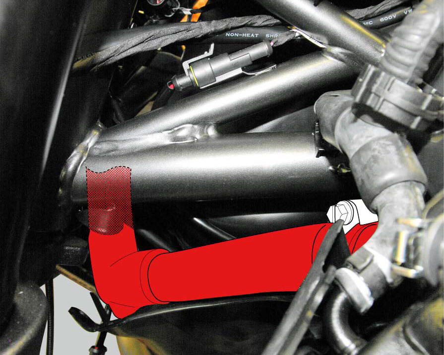
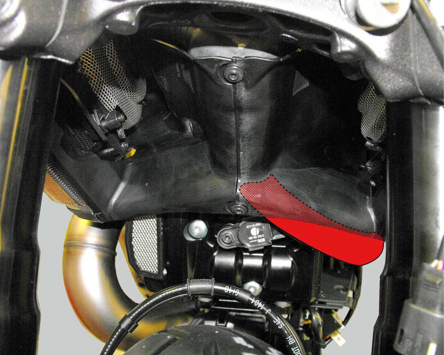
Fix the breather pipe (26) to the radiator/plug sleeve (24) and to the left radiator by tightening the clips (25) and (43) to a torque of 1 +/- 10% (sect. 3 - 3, Frame torque settings).
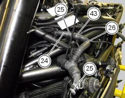
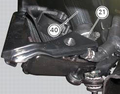
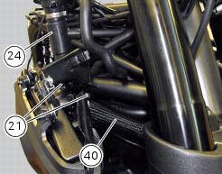
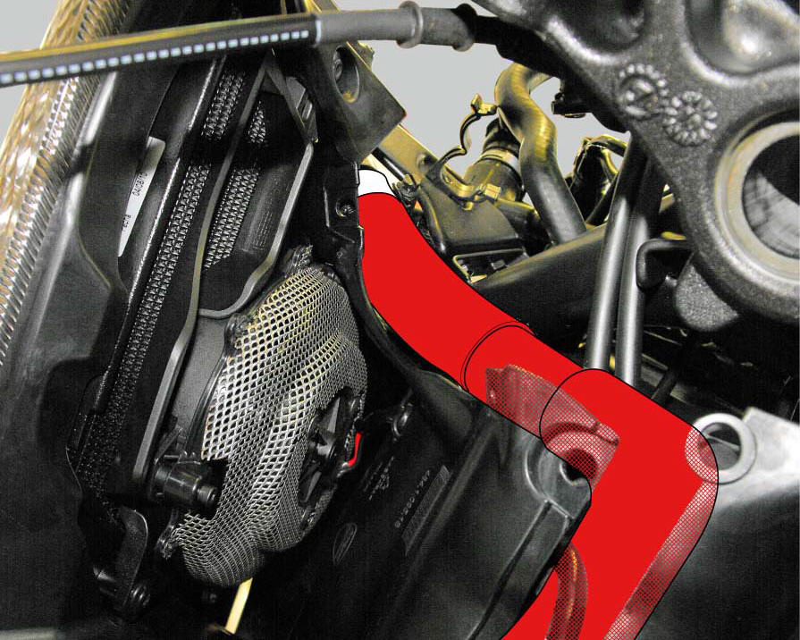
Position the radiator/thermostat sleeve (40) with the clips (21) and the radiator/plug sleeve (24) on the radiators and tighten the clips to a torque of 2.5 +/- 10% (Sect. 3 - 3, Frame torque settings).
Positioning the cooling system tubes
 Removal of the cooling system hoses and unions
Loosen the clips (21) that secure the radiator/thermostat sleeve (40) and the
radiator/plug sleeve (24) to the water
radiators.
Loosen clips (25) and (43) that secure the breather pipe ...
 Water radiators
Clip nut
Spacer
Vibration damper mount
Screw
Screw
Spacer
Vibration damper mount
Clip nut
Bush
Spacer
Rear sprocket
Screw
Water radiator (right)
Screw
Screw
Air de ...
Other materials:
Specific tools for the frame
88713.1072 Drift to install half bearing in bottom yoke
88713.2562 Chain assembly tool
88713.1058 Wrench for steering shaft nut
88713.1062 Tool for installing steering head bearings
88713.2951 Rear wheel balancing tool
88713.3211 Wrench for adjustment of the eccentric hu ...
Battery
Battery safety rules
Warning
Before carrying out any operations on the battery, keep in mind the
safety standards (sect. 1 - 3, General safety rules).
When under charge, batteries produce explosive gases. Keep batteries away from
heat sources, sparks or open flames.
Instructions for use
T ...
Immobilizer override procedure
This procedure makes it possible to "temporarily" turn on the motorcycle if
the hf (hands free) system is not working.
Note
The pin code function must be activated by entering your 4 digit pin in
the dashboard, otherwise the vehicle cannot be
turned on temporarily in the case of a malfunction ...