
Ducati Diavel Service Manual: Refitting the starter motor gear
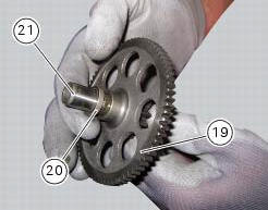
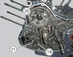
Position the washer (20) and the gear (19) in the pin (21) and take the pin into contact with the crankcase half.
 Removal of the starter motor idler gear
Slide the gear pin (21) complete with the gear (19) and washer (20).
Warning
Pay attention to the washer (20) since it may fall inside the
crankcase half.
At this point, it is possibl ...
 Crankcase halves
Bearing
Bearing holder bushing
Alternator-side crankcase half
Bearing
Circlip
Washer
Bearing
Sealing ring
Bearing
Retaining plate
Screw
Screw
Clutch-side crankcase half
...
Other materials:
Vehicle pre-delivery
Transport packaging integrity check (if required);
Removal from the transport packaging (if required);
Motorcycle integrity check;
Check of the supplied kit completeness (refer to the parts list supplied
together with the bike packaging);
Only if the bike is supplied in a crate: handle ...
Immobilizer override procedure
This procedure makes it possible to "temporarily" turn on
the motorcycle if the hf (hands free) system is not working.
Note
The pin code function must be activated by entering
your 4 digit pin in the instrument panel, otherwise the
vehicle cannot be turned on temporarily in the case ...
Overall dimensions (mm)
Weights
Weight in running order without fluids and battery: 210 kg.
Carrying full load: 400 kg.
Warning
failure to observe weight limits could result in poor
handling and impair the performance of your motorcycle, and
you may lose control of the vehicle.
Important
Do not use addi ...