
Ducati Diavel Service Manual: Removal of the control unit
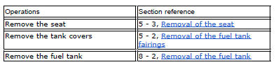
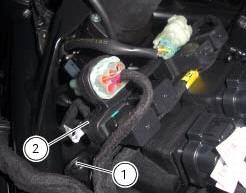
Loosen the screws (1) and remove the relay supporting bracket (2), disconnect the connectors (3) and remove the control unit (4) from the vehicle.
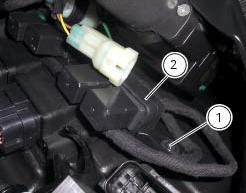
 Layout of engine control system and other components
Injection relay
Etv relay (throttle valve operating engine)
Fan radiator relay
Hands free relay
Ecu
...
 Reassembly of the control unit
Insert the control unit (4) into the protecting sheath (5) and position it on
the airbox.
Position the relay supporting bracket (2) by starting and tightening the
screws (1) to a torque of 6 ...
Other materials:
High engine coolant temperature
The activation of this (amber yellow) "warning" indicates
that the engine coolant temperature is high.
It is activated when the temperature reaches 121C (250f).
Note
In this case, ducati recommends stopping and shutting
off the engine immediately; make sure that the fans are
workin ...
Water pump
Screw
Washer
Circlip
Water pump outlet union
Bearing
bearing
Spacer
Aluminium gasket
Mechanical seal
Water pump impeller
Bush
Water pump cover assembly
Screw
Plug
Sealing washer
Generator cover
Special washer
Fuel filler flange
Spare parts catalogue
Diave ...
Ground connection locations
The negative cable, which is normally connected to the negative pole of the
battery, is fastened to the crankcase. From here, the cable
branches off and splits up within the electrical system to carry the ground
connection to the different elements in the system.
The image shows the ground ...