
Ducati Diavel Service Manual: Abs diagnosis
Note
The on-screen icons used during this procedure are explained in a table at the end of this section.
If the abs system is not working correctly, system diagnosis is possible through the dds diagnosis instrument.
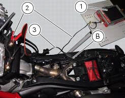
Turn on the dds diagnosis instrument (1) referring to the paragraph "tester power supply": use the power cord (2) part no. 97900.0230.
Connect the power supply cable (3) part no.97900.0227 Tot he power cord (2) part no. 97900.0230 And to the abs diagnosis connector (b) on the frame.
 Deactivating the service indication on the dashboard
The message "serv" is displayed on the dashboard, indicating that the
motorcycle should be serviced in accordance with
the programmed maintenance plan. This indication is activated after the first ...
 Icons table
...
Other materials:
Tester power supply
The dds (1) part number 97900.0215 Can be powered from the vehicle as
follows:
From the mains power supply: by connecting the power supply connector
(n) to the network power supply (2) part no.
97900.0224;
From the motorcycle: connecting the corresponding cables (see paragraph
...
Refitting the airbox and throttle body
Position the filter box (1).
Operate on the vehicle lh side, connect connector (f) of the tps/div motor.
Operating on the right side of the vehicle, connect connector (e) from the
aps sensor.
Check for the vibration dampers (20) on the map sensor supporting bracket
(19).
Insert t ...
Overhaul of the flywheel-alternator assembly
Examine the inner part of alternator rotor (24) for signs of damage. Check
that the starter clutch is working properly and
that the needle races do not show signs of wear or damage of any kind. If there
is any malfunction, remove the whole
assembly.
Disassembling the generator flywheel
U ...