
Ducati Diavel Service Manual: Accelerator position sensor (throttle grip)
Introduction
An accelerator position sensor (aps) is mounted on the throttle body of the diavel, which measures the degree of aperture of the throttle grip.
- The throttle grip is connected to the sensor via two metal cables
- The sensor transmits information to the ecu relative to the "torque demand" made by the rider by twisting the throttle grip.
- For safety reasons, the sensor contains two potentiometers (a main potentiometer - main - and a secondary potentiometer - sub) with independent 5v power and ground.
Component assembling position
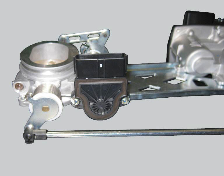
The accelerator position sensor is mounted on the throttle body and is held in place by two screws.

Location of accelerator position sensor connection.
Connection wiring diagram
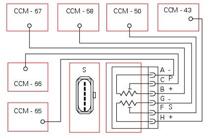
Ccm engine control connection, s accelerator position sensor.
Main potentiometer (p): c orange signal - o, b supply (5v) brown/red - bn/r, a ground black/orange - bk/o.
Secondary potentiometer (s): f signal, green/black - g/bk, h supply (5v) brown/black - bn/b, g ground, black/white bk/w.
The two central pins d and e of the aps connector are not connected.
In the event of fault
In the event of an accelerator position sensor fault, the ecu disables the ride-by-wire system and the engine will not start, remains running at idle or stops.
Fault codes generated and possible correlated faults
Fault codes generated by the engine control unit and displayed by the dds (accelerator position sensor diagnosis):
- Short circuit to vdc: check integrity of electric circuit and electrical connections.
- Short circuit to ground: check integrity of electric circuit and electrical connections.
- Open circuit: check integrity of electric circuit and electrical connections.
- Incorrect electrical characteristics: check integrity of electric circuit and electrical connections. If the above measures do not resolve the fault, contact ducati.
Note
Check integrity of electric circuit - short-circuit to vdc = with dashboard on, using a voltmeter, a voltage is measured between the wire tested and ground.
Check integrity of electric circuit - short-circuit to ground = with the battery cables disconnected, using an ohmmeter, continuity is detected between the wire tested and ground.
Check integrity of electric circuit - open circuit = with the battery cables disconnected, using an ohmmeter, no continuity is detected between the two ends of the wire tested.
The dashboard service display shows the error "accelerator position" and the eobd warning light activates.
Possible correlated faults: inadequate engine power, incorrect idle speed (target idle speed is 1350 rpm with engine stabilised at operating temperature).
Check:
- That the metal cables operating the roller connected to the accelerator position sensor are correctly adjusted so that the roller can reach both the fully closed (throttle grip released) and fully open (throttle grip fully twisted) positions.
Throttle grip aperture may be checked using the dds.
If none of the tests described above identify the problem and the accelerator position sensor is in proper working order, contact ducati.
Component replacement methods
The aps sensor cannot be replaced individually. In case of fault it will not be necessary to replace the whole throttle body (see "operating principle and characteristics of the ride-by-wire system" of this section).
Correctly adjust the cables connecting the throttle grip to the throttle grip position sensor
 Engine speed-timing sensor
Introduction
The engine control system of the diavel is equipped with an inductive sensor
that allows the ecu to determine the speed
and timing phase of the engine. The sensor faces a phonic wheel ...
 Throttle valve position sensor
Introduction
The throttle valve position sensor (tps) of the diavel is mounted on the
throttle body.
The sensor is integrated into the throttle valve actuator motor, which
turns the spindle ...
Other materials:
Parking
Park the stopped motorcycle on the side stand.
Turn the handle completely to the left or right.
If this operation is performed within 60 seconds after the
engine stop, the message "waiting for lock" (fig. 120) Will
appear on the display of the instrument panel for approx.
5 Seco ...
Adjusting the clutch lever and front brake lever
The clutch lever (1) is fitted with a span adjuster (2) which serves to alter
the distance of the lever from the handlebar.
The lever distance can be adjusted through 10 clicks of the dial (2). Turn
clockwise to increase lever distance. Turn the
adjuster counter clockwise to decrease lever d ...
Refitting the swingarm
Apply the recommended threadlocker to the screws (7).
Install the lower chain guard (15) on the swingarm (8), fastening it with the
screws (7): tighten the screws (7) to a torque
of 4 nm +/- 10% (sect. 3 - 3, Frame torque settings).
Locate the swingarm (8) on the frame.
Lubricate with ...