
Ducati Diavel Service Manual: Adjusting of the air-gap phonic wheel sensor
(For front as well as rear sensor) in each case of maintenance that foresees:
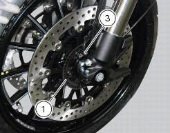
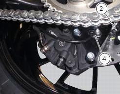
- Replacement or refitting of the wheel
- Replacement or refitting of the phonic wheel (1) or (2)
- Replacement or refitting of the brake discs
- Replacement or refitting of the speed sensor (3) or (4)
- (Front) replacement or refitting of the sensor holder bracket
- (Rear) replacement or refitting of the calliper holder bracket
It is necessary to check the air-gap between the speed sensor and the phonic wheel, once the components are refitted.
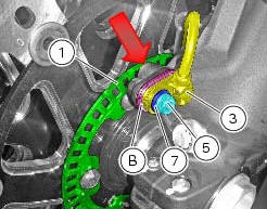
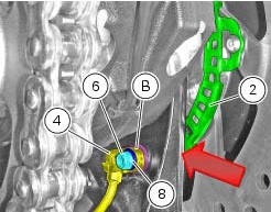
Place the appropriate number of shims (b) under the abs sensor so as to achieve 1.3 To 1.9 Mm air-gap between abs sensor and phonic wheel. When shimming is correct, a 1.3 Mm feeler gauge will fit between abs sensor and phonic wheel, whereas a 1.9 Mm will not.
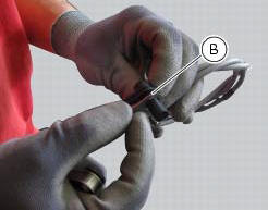
Check at three equally spaced locations (spaced about 120 apart) of the phonic wheels (1) and (2). Shims (b) come in two sizes: 0.2 Mm and 0.5 Mm. Combine the shims as required to achieve correct shimming.
When checking with the 1.3 Mm feeler gauge (go gauge) and the 1.9 Mm feeler gauge (no-go gauge), the abs sensors (3) and (4) must be firmly secured in their seats. This means you need to loosen and retighten the sensor retaining screw fully home with its washer each time you add or remove any shims.
Warning
For the front wheel abs sensor (3), total shims used must never exceed 3 mm on the base version and 3.7 Mm on the carbon version.
For the rear wheel abs sensor (4), total shims used must never exceed 3 mm.
After shimming, tighten the retaining screws (5) and (6) of the sensors (3) or (4) to a torque of 10 nm +/- 10% (sect. 3 - 3, Frame torque settings) placing washers (7) and (8) in-between and check again using the 1.3 Mm feeler gauge (go gauge) and the 1.9 Mm feeler gauge (no-go gauge).
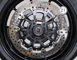
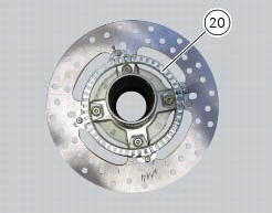
Phonic wheels cleaning
It is important to check that both phonic wheels (21) and (20) are always clean.
Otherwise: gently remove any possible dirt deposits with a cloth or metal brush. Avoid using solvents, abrasives and air or water jets directly on the phonic wheel (21) or (20).

 Bleeding of the abs hydraulic system
If some "sponginess" is detected on the brake control, due to air bubbles in
the system, bleed the system, as indicated in
sect. 4 - 3, Changing the brake fluid.
Before bleeding a brake pump, mo ...
Other materials:
Instrument panel diagnosis
This function identifies any abnormal vehicle behaviours.
The instrument panel activates any abnormal vehicle
behaviours in real time (errors).
At key-on (at the end of the check) one or more "errors"
are displayed in red (only if they are active).
When an "error" is t ...
Removal of the clutch master cylinder assembly
Warning
The clutch master cylinder manufacturer advises against servicing of
the clutch master cylinder (1) due to the safetycritical
nature of this component. Incorrect overhaul of this component could endanger
rider safety.
Maintenance operations of the master cylinder are limited to replac ...
Trip 2 meter
This function shows the distance travelled since the trip meter was last
reset (in km or miles depending on the specific
application).
Press and hold (1) "s" for 3 seconds while in this function to reset the trip
odometer.
When the reading exceeds 9999.9, Distance travelled is reset and t ...