
Ducati Diavel Service Manual: Adjusting the front fork
The front fork used on this motorcycle has rebound, compression and spring preload adjustment.
This adjustment is done using the outer adjusters:
- Rebound damping;
- Inner spring preload;
- Compression damping.
Park the motorcycle in a stable position on its side stand.
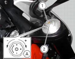
Turn the adjuster (1) on fork leg top with a flat screwdriver to adjust rebound damping.
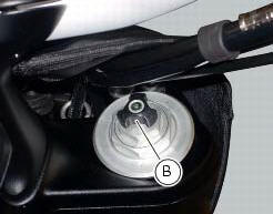
On the carbon model, adjustment is done using the knob (b) on the fork leg, without a screwdriver.
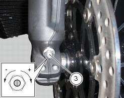
Turn the adjuster (3) on fork leg bottom with a flat screwdriver to adjust compression damping.
As you turn the adjusters (1) and (3), you will hear them click. Each click corresponds to different damping setting.
The stiffest damping setting is obtained with the adjuster turned fully clockwise to the "0" position. Starting from this position, turning counter clockwise, you can count the turns.
To change preload of the spring inside each fork leg, turn the hex. Adjuster (2) with a 22 mm hexagon wrench, starting from the fully open position (clockwise). From reference (a), every full turn clockwise corresponds to 1 mm of preload of the spring, up to a maximum of 15 mm, corresponding to 3 full turns.
Standard settings, from fully open position, are as follows: compression: 1 turn and a half; rebound: 1 and a half turns.
Spring preload: fully open (counter clockwise).
Important
Adjust both fork legs to same settings.
 Adjusting the position of the gear change and rear brake pedals
The position of the gear change and rear brake pedals in relation to the
footrests can be adjusted to suit the preferred
riding position.
To modify the gear change pedal position act in the foll ...
 Adjusting the rear shock absorber
The adjuster (1) located on the lower connection holding the shock absorber
to the swingarm adjusts the damping during
the rebound phase (return).
The knob (2), located on the left side of the m ...
Other materials:
Backlighting setting function for the dashboard on handlebar - dashboard 2
This function allows backlighting setting of the dashboard on handlebar.
To access the function it is necessary to view the ""setting" menu", using
buttons (1) "s" or (2) "t" select the "back
light" function and press the reset button (3) to enter the following page.
Use button (1) "s" or ( ...
The battery charging circuit and power distribution
On the diavel, the +15v (key on power) voltage does not come from a
conventional ignition key, but from pin 30 of the
hands free relay. This relay is switched to closed state by the hands free unit
when the latter enables power on for the
ignition and engine. The hands free relay receives +30v ...
Checking the coolant level
To the specified intervals in the "scheduled maintenance chart" (sect. 4 - 2)
Check the coolant level contained in
the expansion reservoir, on the right side of the vehicle.
The coolant level must be between the max. And min marks on the tank.
If the level is low, top up with the recommende ...