
Ducati Diavel Service Manual: Adjusting the position of the gear change and rear brake pedals
The position of the gear change and rear brake pedals in relation to the footrests can be adjusted to suit the preferred riding position.
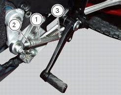
To modify the gear change pedal position act in the following mode: hold the linkage (1) and slacken the counter nuts (2) and (3).
Note
Nut (2) has a left-hand thread.
Fit an open-end wrench to hexagonal element of linkage (1) and rotate until setting pedal in the desired position.
Tighten both check nuts onto linkage.
To adjust the position of the rear brake pedal, proceed as follows.
Loosen counter nut (4).
Turn pedal travel adjusting screw (5) until pedal is in the desired position.
Tighten the counter nut (4).
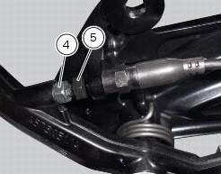
Work pedal by hand to make sure it has 1.5 - 2 Mm free play before brake begins to bite.
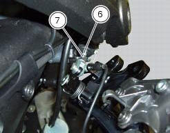
If not, check to modify the length of the cylinder push-rod in the following mode.
Slacken off the counter nut (7) on the pushrod.
Screw the rod into the fork (6) to increase play, or unscrew it to reduce play.
Tighten the counter nut (7) and recheck the pedal free play.
 Adjusting the clutch lever and front brake lever
The clutch lever (1) is fitted with a span adjuster (2) which serves to alter
the distance of the lever from the handlebar.
The lever distance can be adjusted through 10 clicks of the dial (2). T ...
 Adjusting the front fork
The front fork used on this motorcycle has rebound, compression and spring
preload adjustment.
This adjustment is done using the outer adjusters:
Rebound damping;
Inner spring preload;
Co ...
Other materials:
Topping up the electrolyte
Warning
Before carrying out any operations on the battery, keep in mind the
safety standards (sect.1 - 3, General safety rules).
The electrolyte in the battery is toxic and can cause burns if it comes into
contact with the skin because it contains
sulphuric acid. Wear protective clothing, a ...
Storing the bike away
If the motorcycle is to be left unridden over long periods, it is
advisable to carry out the following operations before storing
it away:
clean the motorcycle;
empty the fuel tank;
pour a few drops of engine oil into the cylinders through the
spark plug bores, then turn the engine over by hand ...
Injection and ignition
Introduction
Ignition is via a single stick coil per cylinder installed in the spark plug
well. Each thermal unit is supplied by a single
injector, placed under the throttle valve. The amount of fuel injected and the
ignition advances are determined by the
control unit specifically for each c ...