
Ducati Diavel Owners Manual: Adjusting the position of the gearchange and rear brake pedals
The position of the gearchange and rear brake pedals in relation to the footrests can be adjusted to suit the requirements of the rider.
Adjust the pedals as follows:
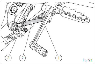
Gear change pedal (fig. 97) Hold the linkage (1) and slacken the lock nuts (2) and (3).
 Note
Note
Nut (2) has a left-hand thread.
Fit an open-end wrench to hexagonal element of linkage (1) and rotate until setting pedal in the desired position.
Tighten both check nuts onto linkage.
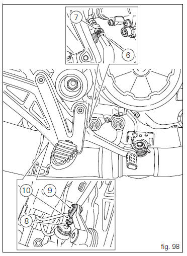
Rear brake pedal
Loosen counter nut (7).
Turn pedal stroke adjusting screw (6) until pedal is in the desired position.
Tighten the counter nut (7).
Operate the pedal by hand to check that there is 1.5 To 2 mm of freeplay before the brake bites.
If not, adjust the length of the master cylinder pushrod as follows.
Slacken off the counter nut (10) on the pushrod.
Screw the pushrod (8) into the front fork (9) to increase the freeplay, or screw it out to reduce it.
Tighten the counter nut (10) and recheck the pedal freeplay.
 Gear change pedal
When released, the gear change pedal (1, fig. 96)
Automatically returns to rest position n in the centre. This is
indicated by the instrument panel light n (2, fig. 4) Coming on.
The pedal can be ...

Other materials:
Refitting the gearchange mechanism
Make sure that the gearchange linkage assembly (6) is installed with the ball
joint with a left-hand thread (a) facing the
lever (8).
Apply the recommended grease to the non-threaded surface of the pin (4).
Fit the first o-ring (5) in the pin (4).
Start the pin (4) in the gearchange leve ...
Hands free
Hands free
Special screw
Plug
Electric fuel plug
Button
Spring
Frame
Elastic pin
Spare parts catalogue
Diavel abs handlebar and controls
Diavel carbon
abs
handlebar and controls
Important
Bold reference numbers in this section identify parts not shown in the
figures a ...
Rh switch
Red on/off switch.
Black engine start button.
The switch (1) has three positions:
Centre: run off. In this position, the engine cannot be
started and all electronic devices are off.
Pushed down: on/off. In this position, the system can
be turned on (key-on) and off (key-off).
Pus ...