
Ducati Diavel Owners Manual: Adjusting the rear shock absorber
The rear shock absorber has external commands that enable you to adjust the setting to suit the load on the motorcycle.
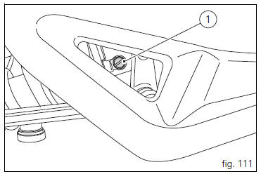
The adjuster (1, fig. 111) Located on the lower connection holding the shock absorber to the swingarm adjusts the damping during the rebound phase (return).
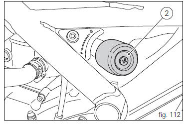
The knob (2, fig. 112), Located on the left side of the motorcycle, adjusts the preload of the shock absorber external spring.
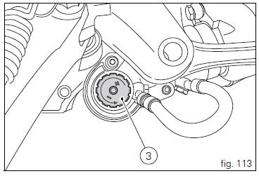
The knob (3, fig. 113) Located on the expansion reservoir of the shock absorber adjusts the damping during the compression phase.
Turning the adjusters (1) or the knobs (2) and (3) clockwise to increase preload damping; they decrease turning them in the opposite direction.
Standard setting; from fully closed (clockwise) loosen: adjuster (1, fig. 111) By 12 clicks; knob (2, fig. 112) Fully open (counter clockwise); adjuster (3, fig. 113) By 25 clicks.
 Warning
The shock absorber is filled with gas under pressure and may cause severe damage if taken apart by unskilled persons.
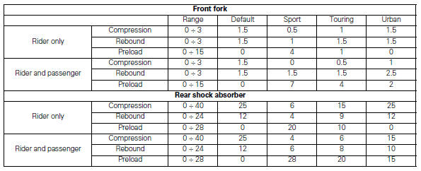
When carrying a passenger and luggage, set the rear shock absorber spring to proper preload to improve motorcycle handling and keep safe clearance from the ground. It may also be necessary to adjust the rebound damping accordingly.
Values specified in the table are indicative and refer to a rider
Weighing (with clothes on) 80-90kg and a passenger
Weighing (with clothes on) 70-80kg.
 Adjusting the front fork
The front fork used on this motorcycle has rebound,
compression and spring preload adjustment.
The settings are adjusted using external adjuster screws.
To adjust rebound damping (fig. 109);
...

Other materials:
Removing the water radiators
Loosen the screws (p) that retain the supports (s) of the front splashguard
to the air ducts (24) and (26).
Loosen the screws (30), to separate the two internal air ducts (24) and (26).
Disconnect the wiring connectors of the main wiring loom (c) from both fans.
Disconne ...
Absolute pressure sensors
Introduction
The engine control system of the diavel is equipped with two absolute
pressure sensors, with one connected to the intake
duct of each cylinder (map 1 cylinder 1 - horizontal - map 2 cylinder 2 -
vertical). They are used by the control unit to
determine the quantity of fuel to be ...
Menu 2 on/off function
This function turns off and back on the menu 2.
If menu 2 is disabled, the functions for average fuel
consumption (cons.Avg), instantaneous fuel consumption
(cons.), Average speed (speed avg), trip time (trip time)
and air temperature (air) will no longer be displayed in the
"main screen ...