
Ducati Diavel Service Manual: Adjusting the rear shock absorber
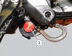
The adjuster (1) located on the lower connection holding the shock absorber to the swingarm adjusts the damping during the rebound phase (return).
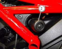
The knob (2), located on the left side of the motorcycle, adjusts the preload of the shock absorber external spring.
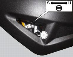
Turn the adjuster (1) clockwise to increase damping h; or counter clockwise to reduce damping s.
Standard setting from the fully closed position (clockwise): -unscrew adjuster (1) by 8 clicks.
Spring preload: 15 mm.
The two nuts (2) on the upper part of the shock absorber serve to adjust the preload on the external spring. To change spring preload, slacken the upper locking ring nut. Then tighten or slacken the lower ring nut to increase or decrease spring preload.
Important
The knob (3) located on the expansion reservoir of the shock absorber adjusts the damping during the compression phase.
Turning the adjusters (1) or the knobs (2) and (3) clockwise to increase preload damping; they decrease turning them in the opposite direction.
Standard setting: from fully closed (clockwise) loosen: register (1) of 12 clicks; knob (2) fully open (counter clockwise); register (3) of 25 clicks.
Spring preload: 18 mm (max.18 Mm - min.25 Mm
Warning
The shock absorber is filled with high-pressure gas and can cause injuries if inexpertly dismantled.
Important
If the motorcycle is to be ridden with a pillion rider and luggage, we
recommend setting the rear shock absorber spring
preload to the maximum to ensure the best handling and proper ground clearance
at all times. It may also be necessary
to adjust the rebound damping accordingly.
 Adjusting the front fork
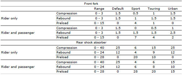
The front fork used on this motorcycle has rebound, compression and spring
preload adjustment.
This adjustment is done using the outer adjusters:
Rebound damping;
Inner spring preload;
Co ...
 Fairings
...
Other materials:
Transmission
Wet clutch controlled by the lever on left-hand side of the
handlebar.
Transmission from engine to gearbox primary shaft via spur
gears.
Front chain sprocket/clutch gearwheel ratio:
33/61
6-speed gearbox with constant mesh gears, gear change
pedal on left side of motorcycle.
Gearbox ou ...
Steering release error - steering still locked
The activation of this (amber yellow) "warning" indicates
that the hands free system was not able to extract the
steering lock.
Warning
In this case, ducati recommends turning the vehicle
off and on (key-off / key-on) holding the handlebar pressed
down to the end stop. If the signal ...
Useful information for safe riding
Warning
Read this section before riding your motorcycle.
Many accidents are the result of the inexperience of the
rider. Always make sure you have your licence with you; you
need a valid licence that entitles you to ride a motorcycle.
Do not lend your motorcycle to persons who are
inexperie ...