
Ducati Diavel Service Manual: Air temperature sensor
Introduction
The engine control system on the diavel uses a sensor that measures air temperature. This sensor has a resistance of ntc type (negative temperature coefficient), that reduces its own value when the temperature increases. The air temperature sensor allows the engine control unit to modify the fuel-air mixture and ignition advance in relation to the atmospheric air temperature.
Components assembling position
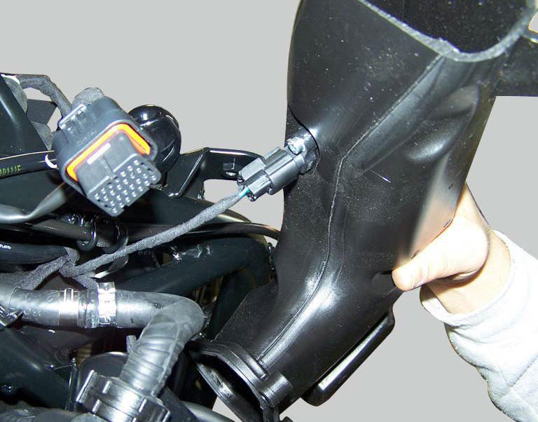
The air temperature sensor is mounted on the right hand air intake (the image also shows the location of the connection).
Wiring diagram
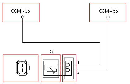
Ccm engine control connection, s air temperature sensor. 1 Green/blue - g/b, 2 black/purple - bk/v.
In the event of fault
In the event of an air temperature sensor fault, the engine control unit implements a recovery value of 25C.
Fault codes generated and possible correlated faults
Fault codes generated by the engine control unit and displayed by the dds (intake air temperature sensor diagnosis):
- Short circuit to vdc: check integrity of electric circuit and electrical connections.
- Short circuit to ground: check integrity of electric circuit and electrical connections.
- Open circuit: check integrity of electric circuit and electrical connections.
Note
Check integrity of electric circuit - short-circuit to vdc = with dashboard on, using a voltmeter, a voltage is measured between the wire tested and ground.
Check integrity of electric circuit - short-circuit to ground = with the battery cables disconnected, using an ohmmeter, continuity is detected between the wire tested and ground.
Check integrity of electric circuit - open circuit = with the battery cables disconnected, using an ohmmeter, no continuity is detected between the two ends of the wire tested.
The dashboard service display shows the error "air temperature" and the eobd warning light activates.
Possible correlated faults: inadequate engine power, irregular idle speed (target idle speed is 1350 rpm with engine stabilised at operating temperature), the engine does not start easily. Check: -sensor resistance, which must be approximately 2 kohm at 25 C.
The air temperature value may be checked using the dds. Check that the value given is plausible.
If none of the aforementioned tests identify the problem and the air temperature sensor is in proper working order, replace the engine control unit.
Component replacement methods
No special measures are necessary in order to replace the air temperature sensor.
 Component assembling position
The throttle valve position sensor is integrated in the throttle valve
actuator motor.
Location of electric connection for throttle valve actuator motor - tps
(throttle valve position sen ...
 Engine temperature sensor
Introduction
The engine control system on the diavel uses a sensor that measures the
temperature of the coolant (engine
temperature). This sensor has a resistance of ntc type (negative temperature ...
Other materials:
Indicator air - air temperature
This function shows the external temperature.
Display limits: -39C - +124C
In the event of a sensor fault (-40C, +125C or disconnected), a string of
dashes "- - -" (not flashing) is displayed and
the "vehicle/engine diagnosis - eobd" light comes on.
Note
When the vehicle is stopped, the ...
Checking drive chain tension
Important
Have chain tension adjusted by a ducati dealer or
authorised service centre.
Make the rear wheel turn until you find the position where
chain is tightest.
Set the vehicle on the side stand. Push down the chain at the
point of measurement and release.
Measure the distance betwee ...
Refitting the front brake system
While refitting the system, pay special attention to the orientation of the
pipe couplings (24) on the pump and the pipes
(13) and (20) on the callipers (9) and (18).
Warning
If incorrectly positioned, the hose can affect brake operation and
foul moving parts. Position the hose as shown in th ...