
Ducati Diavel Service Manual: Alternator
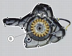
It is equipped with a 12 v, 430 w generator, consisting of a fixed element (stator, a) located on the generator cover and of a movable element (rotor, b) fixed to the crankshaft.
Note
To check the battery charging system for faults, use the dds diagnosis instrument and follow the instructions given in the paragraph, "testing the battery charging system" (sect. 6 - 11).
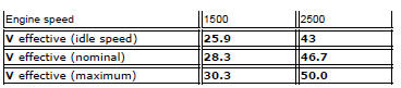
The absolute value of voltage measured across the terminals of two of the three yellow cables (the measured value will be the same whichever combination of cable is used) must be within the range indicated in the table below.
(Ambient temperature: 35 C - 70 C)
Important
Before testing, disconnect the alternator wiring from the electrical system when the ignition key is set to off.
Values significantly lower than those indicated above can be due to:
- Partially demagnetised rotor;
- Short-circuited windings.
In the above cases the whole alternator assembly (rotor and stator) should be renewed.
If checks have a favourable outcome, reconnect the alternator to the regulator with ignition key on off. Make sure that no cables are damaged or disconnected.
Removal of the alternator
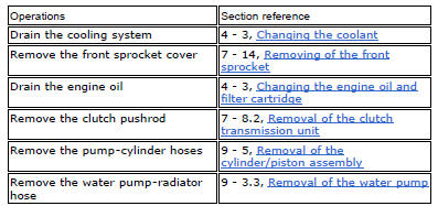
Disconnect the cables of the alternator-side electric system (sect. 6 -1, Routing of wiring on frame).
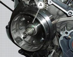
Remove the generator cover, the stator (a) and the rotor (b) (sect. 9 - 8, Removal of the generator cover).
Refitting the

Refitting the generator
Fit the rotor (b), the stator (a) and the alternator-side crankcase cover.
Connect the cables of the generator side electric system (refer to the table in chapter "routing of wiring on frame", sect. 6 - 1).

 Battery
Battery safety rules
Warning
Before carrying out any operations on the battery, keep in mind the
safety standards (sect. 1 - 3, General safety rules).
When under charge, batteries produce explo ...
 Rectifier-regulator
The rectifier (1) is placed in the electrical components compartment.
The rectifier/regulator consists of an aluminium casing containing the diodes
that rectify the current produced by the
alter ...
Other materials:
Coverage
Warranty defects shall be remedied during customary
business hours at any authorized ducati motorcycle dealer
located within the united states of america in compliance
with the clean air act and applicable regulations of the
united states environmental protection agency and the
california air r ...
How to turn the motorcycle off
To turn the motorcycle off, turn the switch from "run on" to "run off". The
engine stops. To switch the dashboard off,
push the on/off switch downwards. When released, the switch automatically
returns to the "run off" position.
Push the switch downwards to switch the engine off and enter " ...
Reassembly of the crankcase halves
The crankcase halves must be in good condition and perfectly clean. The
mating surfaces must be perfectly flat and free
from burrs.
Overhauling the alternator-side crankcase half
The following parts must be present on the internal side of the crankcase
half:
Gearbox secondary shaft bearin ...