
Ducati Diavel Service Manual: Appropriate diagnosis tools
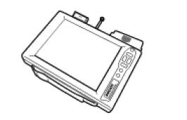
97900.0211 Dds (ducati diagnosis system) without cables
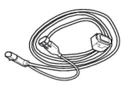
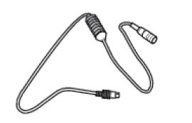
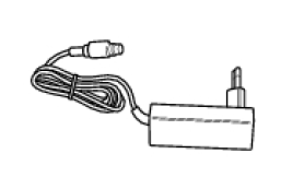
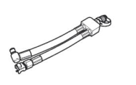
97900.0227 Power cable and diagnosis
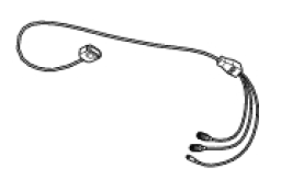
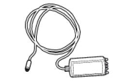
97900.0222 Power cable and diagnosis 1060838 (measurement module)
97900.0218 Vacuum sensor
552.1.039.1A Pressure sensor
97900.0220 Pressure/vacuum tube
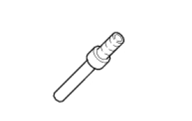
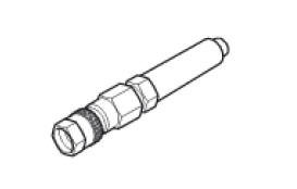
97900.0221 Union
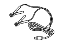
97900.0228 Battery socket adapter
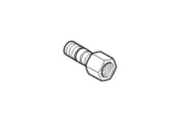
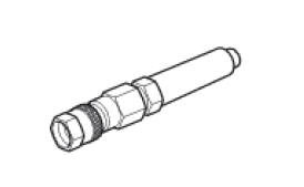
814.1.114.1A Oil pressure coupling
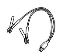
514.1.032.1A Auxiliary test cable
552.1.038.1A Cylinder compression cable m10 fitting
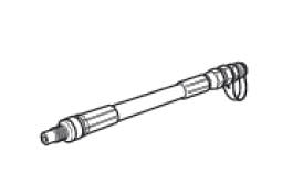
875.1.065.1A Oil pressure tube
97900.0230 Feeder
97900.0224 Feeder
88765.1371 Belt tensioning sensor
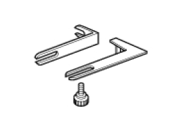
88765.1374 Belt tensioning sensor bracket
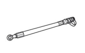
590.1.189.1A Fuel pressure tube
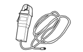
88765.1126 Clamp-type amperemeter
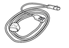
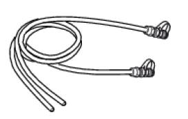
97900.0227S Can network diagnosis cable
 Specific tools for the frame
88713.1072 Drift to install half bearing in bottom yoke
88713.2562 Chain assembly tool
88713.1058 Wrench for steering shaft nut
88713.1062 Tool for installing steering head bearings ...

Other materials:
Refitting the clutch-side crankcase cover
Clean and degrease mating surfaces on the clutch-side crankcase half cover
and crankcase and ensure that locating bush
(12) and the o-ring (11), located in correspondence with the oil way, are
installed in the crankcase.
Apply an even, regular bead of ducati liquid gasket (a) on the mating ...
Disassembly of the gearbox shafts
Place the shaft in a vice in such a way as to facilitate the disassembly
operations.
Important
Take care not to invert the positions of the shims on reassembly:
this would potentially lead to jamming when using the gear selector control,
making it necessary to reopen the engine
crankcase.
D ...
Immobilizer override procedure
This procedure makes it possible to "temporarily" turn on
the motorcycle if the hf (hands free) system is not working.
Note
The pin code function must be activated by entering
your 4 digit pin in the instrument panel, otherwise the
vehicle cannot be turned on temporarily in the case ...