
Ducati Diavel Service Manual: Changing bulbs
Changing the headlight bulbs
Before replacing a burnt out light bulb, ensure that the replacement bulb has the same voltage and power rating as specified for the lighting device in question (sect. 3 - 1.1, Lights/instrument panel).
Warning
The halogen light bulbs in the headlight become hot when switched on and remain hot for some time after they are switched off. Allow bulbs to cool before replacing them.
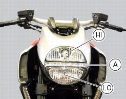
The position of the light bulbs in the headlight is as indicated below: low beam (lo), high beam (hi) and parking light (a).
Remove the headlight, as described in the paragraph "renewal of the headlight" of this section.
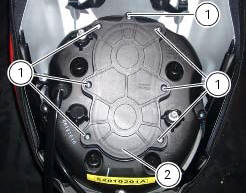
To access the headlight bulbs loosen the screws (1) and remove the cover (2).

High beam (hi)
Disconnect the wiring connector (3) from the headlight bulb (4).
Release the retaining clip (5).
The bulb (4) has a bayonet base: press and twist counter clockwise to remove.
Fit the new bulb (4), insert the tabs on the bulb base into the corresponding slots to ensure the bulb is correctly positioned, push the bulb in and turn clockwise until it clicks into place.
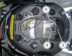
Refit the connector (3) to the lamp (4), the cover (2) to the headlight, then tighten the screws (1).
Low beam (lo)
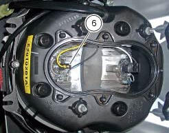
To change the lo beam headlight bulb (6) see the procedure described above for the hi beam headlight bulb.
Replace the lamp with a new one of the same type and rating (sect. 3 - 1.1, Lights/instrument panel).
Note
Do not touch the transparent part of the bulb with your fingers, this will darken it and cause a loss of brightness.
 Renewal of the headlight
Disconnect the headlight connectors (a) from the main wiring (refer to the
tables of paragraph "routing of wiring on
frame", sect. 6 - 1).
Loosen nuts (2) that fix the front optical unit to th ...
 Headlight aim
The motorcycle must be perfectly upright with the tires inflated to the
correct pressure and with a rider seated, perfectly
perpendicular to the longitudinal axis.
Position the motorcycle 10 met ...
Other materials:
Clock setting function
This function sets the clock.
To access the function it is necessary to view the "setting" menu page 48, using
button (1, fig. 14) ?"
"or (2, fig. 14) ?""select the "clock"function and
press the reset button
(12, fig. 12) To confirm.
In the follow ...
"Parking" function
This function activates the "parkin"h mode.
The "parkin"h function activates the front and rear parking
lights when the vehicle is turned off so it is visible when
parked.
The function is activated by pressing the button (2, fig. 14)
?"´" for 3 seconds du ...
Cleaning and replacing the spark plugs
Spark plugs are essential to smooth engine running and
should be checked at regular intervals.
The condition of the spark plugs provides a good indication of
how well the engine is running.
Have the spark plugs inspected or replaced at a ducati dealer
or authorised service centre; they will ...