
Ducati Diavel Service Manual: Changing the clutch fluid
Warning
Clutch fluid will damage painted surfaces if spilled on them. It is also very harmful if it comes into contact with the skin or with the eyes; in the event of accidental contact wash the affected area with abundant running water.
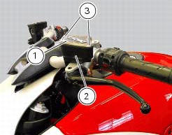
Remove cover (1) and membrane from the clutch fluid reservoir (2) by loosening the screws (3).
Siphon off the fluid from the reservoir (2).
Fill the tank (2) with new oil up to the max. Mark.
Operate the clutch lever two or three times until the circuit is pressurised.
Hold the lever pulled in towards the grip.
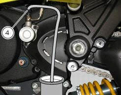
Attach a length of transparent plastic tubing to the bleed valve (4) and insert the other end of the tubing in a container Placed on the floor.
Open the bleed valve (4) to allow fluid to escape.
Warning
During the filling operation, always keep the oil level above the min mark to prevent the formation of air bubbles in the circuit.
Allow the fluid to flow from the bleed valve (4) until it changes colour. Retighten the bleed valve (4) and tighten to a torque of 4 nm +/-10% (sect. 3 - 3, Frame torque settings) and restore the correct level of oil in the tank.
 Changing the brake fluid
Warning
Brake fluid is corrosive and will damage paintwork. Avoid contact
with eyes and skin. In the case of accidental contact,
wash the affected area thoroughly with plenty of running water.
Ch ...
 Draining the clutch hydraulic circuit
Warning
Clutch fluid will damage painted surfaces if spilled on them. It is
also very harmful if it comes into contact with the skin or
with the eyes; in the case of accidental contact, wash the a ...
Other materials:
Dashboard on tank
Menu 1 (tot, trip1, trip2, trip fuel).
Menu 2 (cons.Avg., Cons., Speed avg, air and trip time) if active.
Gear / neutral indication.
Icon referred to the function below from menu 1.
Indication of engine setting for the currently set riding style.
Currently set riding style (riding mode) ...
Changing and cleaning the air filters
The air filter must be replaced at the intervals described in the "scheduled
maintenance chart" (sect. 4 - 2).
Work on the vehicle right side, loosen screws (1) that secure the intake duct
(2) to the filter box, and the radiator
retaining screw (3); recover the washer (4).
Remove the in ...
Starter motor relay
Introduction
When the rider presses the start button, with all the safety conditions
required to enable engine start met, the engine
control unit enables the relay that activates the starter motor.
Component assembling position
Connection on starter motor relay.
Connection wiring diagram
...