
Ducati Diavel Service Manual: Changing the coolant
Warning
This operation must only be carried out when the engine is cold.
Attempting to change the coolant with the engine hot
could lead to burns from hot coolant or scalding steam.
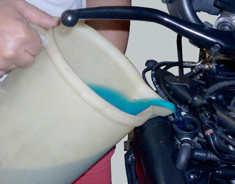
Place a container under the engine and place the motorcycle on its side stand.
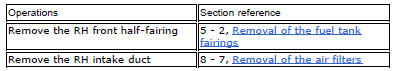
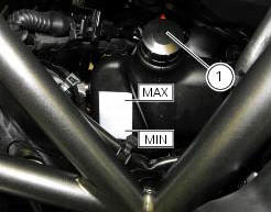
Remove the expansion reservoir filler cap (1).
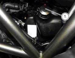
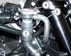
Loosen clip (2), disconnect the hose (3) and drain the coolant inside a container.
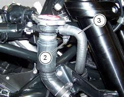
Loosen the cap (4) of the fluid exhaust hole placed on the pump cover.
Allow the coolant to drain off completely.
Screw plug (4) with a seal again in the fluid drain hole, and recover the new seal (5).
Tighten the plug (4) to a torque of 20 nm (min. 18 Nm - max. 22 Nm) (sect. 3 - 3, Engine torque settings).
Refill the circuit by pouring new coolant into the circuit via the remote filler cap (6).
Connect the pipe (3) by tightening the clamp (2) to a torque of 1 nm +/-10% (sect. 3 - 3, Frame torque settings).
Allow several minutes for the coolant to fill all the internal passages.
Start up the engine and allow the coolant to reach 110 C; run the engine for about 10 minutes.
Stop the engine and allow it to cool down so that all the air is expelled from the cooling circuit.
Warning
Keep your hands, clothing and tools well clear of the radiator fan at all times; this fan starts automatically without warning and could cause serious injury or damage.
Important
Check the cooling circuit for possible leaks.
Top up the coolant through the expansion reservoir filler to bring the level up to the max. Mark.
Tighten the cap (1) of the expansion reservoir.
 Checking the coolant level
To the specified intervals in the "scheduled maintenance chart" (sect. 4 - 2)
Check the coolant level contained in
the expansion reservoir, on the right side of the vehicle.
The coolant level mu ...
 Changing the brake fluid
Warning
Brake fluid is corrosive and will damage paintwork. Avoid contact
with eyes and skin. In the case of accidental contact,
wash the affected area thoroughly with plenty of running water.
Ch ...
Other materials:
Oxygen sensors
Introduction
An on-off type oxygen sensor (in normal operating conditions, the voltage
generated by the sensors switches between a
value close to 1v and a value close to 0v) is mounted on each of the exhaust
manifold of the diavel.
Each oxygen sensor has its own internal heater, which recei ...
Check the engine oil pressure
Note
The on-screen icons used during this procedure are explained in a table at
the end of this section.
To measure the pressure of the lubrication circuit, use the engine oil pressure
test point (19) as described below.
Disconnect the wiring connector (f) of pressure switch (1) and rem ...
Riding mode customisation
This function customises each riding style.
To access the function it is necessary to view the "setting"
menu page 48, using button (1, fig. 14) ?
or (2, fig. 14)
? select the "riding mode" function
and press the
reset button (12, fig. 12) To go to next page.
W ...