
Ducati Diavel Owners Manual: Charging the battery
Before charging the battery, it is recommended to remove it from the motorcycle.
 Important
The battery is housed in the cowling, always contact a ducati dealer or an authorised service centre for its removal.
Remove the left cowling (1, fig. 137) Loosening: side screw (2, fig. 137) Retaining the electrical parts box; top screw (3, fig. 137) Retaining the electrical parts box; bottom screw (4, fig. 137) Retaining the central cowling;
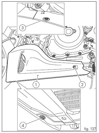
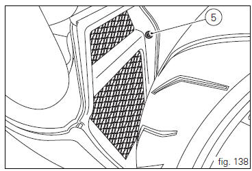
Screw (5, fig. 138) Retaining the central cowling to left cowling.
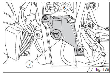
Unscrew the screws (6, fig. 139) And remove the battery mounting cover (7, fig. 139).
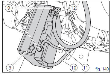
Slide out the battery (8, fig. 140) From its housing and, always starting from the negative terminal (-), loosen the screws (9, fig. 140).
Remove the positive cable (10, fig. 140), The abs positive cable (11, fig. 140) From the positive terminal and the negative cable (12, fig. 140) From the negative terminal.
 Warning
The battery produces explosive gases: keep it away from heat sources and flames.
 Warning
Keep the battery out of the reach of children.
Charge the battery at 0.9 A for 5÷10 hours.
Charge the battery in a well-ventilated area.
Connect the battery charger leads to the battery terminals: red to the positive terminal (+), black to the negative terminal (-).
 Important
Connect the battery to the charger before switching it on; failure to do so can result in sparking at the battery terminals, which could ignite the gases inside the cells.
Always connect the red positive terminal (+) first.
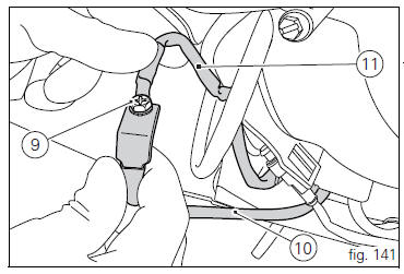
Lay down the abs positive cable (11, fig. 141), Onto positive cable (10, fig. 141) And start screw (9, fig. 141) In its thread on these cables.
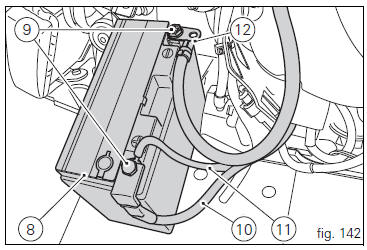
Connect the positive cable (10, fig. 142), Previously assembled to abs cable (11, fig. 142), To battery positive terminal, and negative cable (12, fig. 142) To battery negative terminal, by starting the other screw (9, fig. 142) In its thread.
Tighten the terminal clamp screws (9, fig. 142) To a torque of 5 nm ±10% and apply grease onto the battery terminals to prevent oxidation.
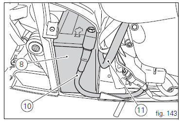
Reposition the battery (8, fig. 143) In the support, positioning the cables (10, fig. 143) And (11, fig. 143) As shown in fig.
143.
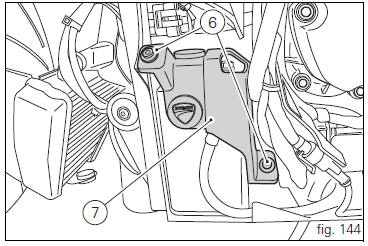
Refit battery mounting cover (7, fig. 144) And fasten tightening the screws (6, fig. 144) To a torque of 10 nm ±10%.
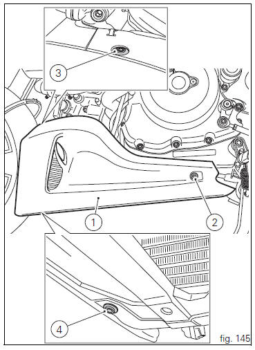
Refit the left cowling (1, fig. 145) As follows: start the side screw (2, fig. 145) Retaining the electrical parts box in its thread; start the top screw (3, fig. 145) Retaining the electrical parts box in its thread; start the bottom screw (4, fig. 145) Retaining the central cowling in its thread;
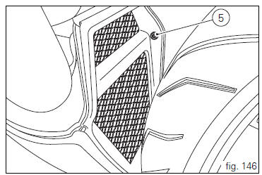
Start the screw (5, fig. 146) Retaining the central cowling to left cowling in its thread.
Tighten the screws (2, fig. 149), (3, Fig. 145), (4, Fig. 145) And (5, fig. 146) To a torque of 10 nm ±10%.
 Adjusting throttle control free play
The throttle twistgrip must have free play of 1.5×2.0 Mm in
all steering positions, measured on the outer edge of the
twistgrip. If necessary, adjust it using the adjusters (1 and 2,
fig. 135 ...
 Charging and maintenance of the battery during winter Storage
Your motorcycle is equipped with a connector (1, fig. 147) To
which you can connect a special battery charger available
from our sales network.
...
Other materials:
Removal of the engine
In order to remove engine you must first remove a series of other components
from the motorcycle.
Most of these removal procedures are described in the relative sections of this
manual.
The following flow chart illustrates the logical sequence in which the parts are
to be removed from th ...
Cleaning and replacing the spark plugs
Spark plugs are essential to smooth engine running and
should be checked at regular intervals.
The condition of the spark plugs provides a good indication of
how well the engine is running.
Have the spark plugs inspected or replaced at a ducati dealer
or authorised service centre; they will ...
Indication of range reached for service
When service coupon threshold is achieved, upon every key-on the system
displays the indication of the type of
intervention that is required (oil service or desmo service).
The (red) warning is activated as a large icon for 10 seconds upon every key-on
(1) then as a small warning that
remai ...