
Ducati Diavel Service Manual: Check the engine oil pressure
Note
The on-screen icons used during this procedure are explained in a table at the end of this section.
To measure the pressure of the lubrication circuit, use the engine oil pressure test point (19) as described below.
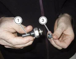
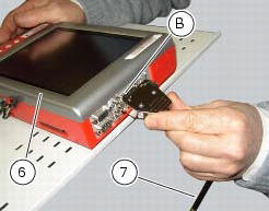
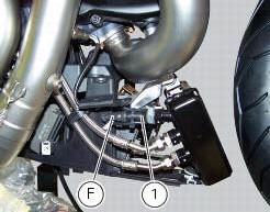
Disconnect the wiring connector (f) of pressure switch (1) and remove it taking care to recover the seal.

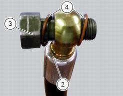
Insert in the pipe union fitting (2) part no. 875.1.065.1A the fitting (3) part no. 814.1.114.1A, by putting the two copper gaskets (4). Fit in the threaded hole the fitting (3) of pipe (2), by tightening it fully home. Refit on fitting (3) the pressure switch (1), with the relevant gasket and reconnect it to connector (f) of the electric system.
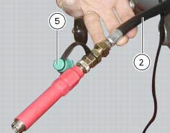
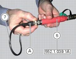
Connect the pressure sensor (5), part no. 552.1.039.1A, to the hose (2), in order to convert the pressure reading into an electric signal.
Turn on the dds diagnosis instrument (6) referring to the paragraph "tester power supply".
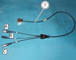
Connect the power and diagnosis cable (measurement module) (7) part no. 97900.0222 To the measurement module connector (b) of the dds (6).
Connect the pressure sensor (5) to socket (a) or (c) of the cable (7).
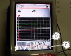
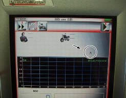
On the dds diagnosis instrument (1), select the "measurement module" function by pressing the corresponding icon; then press the "pressure test" icon (d) followed by the "start" icon (e).

The socket to which the cable (measurement module) (7) is to be connected is indicated on the screen with a capital letter: a, b or c.

Start the engine.
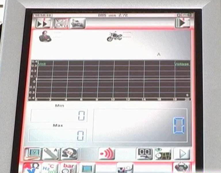
The values may be displayed in three different ways: in one numeric form and in two graphic forms; to select the desired display type, press the "value display" icon.
The measured value is indicated alongside the letter (a) or (c) identifying the cable used for the measurement: i.E. If you used connector (a) of the cable (3), the value measured will displayed next to the letter (a) on the screen.
Oil pressure test values: warm engine
(Minimum oil temperature = 80 C) 1100-1300 min-1
Greater than 0.8 Bar.
3500-4000 Min-1 greater than 4 bar.
Important
The maximum pressure must never exceed 6.0 Bar.
Excessively high pressure may indicate that the relief valve is stuck. Excessively low pressure, on the other hand, may be caused by the relief valve being stuck in the open position, the relief valve spring being too weak, or a faulty oil pump.
Other causes are excessively worn seals and gaskets or a badly worn engine.
Remove the gauges and refit the pressure switch (1) with its seal. Tighten it to a torque of 19 nm +/- 10% (sect. 3 - 3, Frame torque settings).
Connect the electrical system connector (f) to the pressure switch.
Disconnect the dds diagnosis instrument.
 Check the idle and the co amount with warm engine
Start the engine;
Switch on the dds and check that it does not signal any error (otherwise
consult the relevant paragraph of this manual
to reset the error and proceed with the idle check);
...
 Cylinder compression test
Note
The on-screen icons used during this procedure are explained in a table at
the end of this section.
Engine performance is directly correlated to the pressure that can be
measured in the com ...
Other materials:
Refitting the swingarm
Apply the recommended threadlocker to the screws (7).
Install the lower chain guard (15) on the swingarm (8), fastening it with the
screws (7): tighten the screws (7) to a torque
of 4 nm +/- 10% (sect. 3 - 3, Frame torque settings).
Locate the swingarm (8) on the frame.
Lubricate with ...
Hands free
Hands free
Special screw
Plug
Electric fuel plug
Button
Spring
Frame
Elastic pin
Spare parts catalogue
Diavel abs handlebar and controls
Diavel carbon
abs
handlebar and controls
Important
Bold reference numbers in this section identify parts not shown in the
figures a ...
Rectifier-regulator
The rectifier (1) is placed in the electrical components compartment.
The rectifier/regulator consists of an aluminium casing containing the diodes
that rectify the current produced by the
alternator. It also contains an electronic device that regulates the current
supplied by the alternator ...