
Ducati Diavel Service Manual: Checking and adjusting timing belt tension
Note
The on-screen icons used during this procedure are explained in a table at the end of this section.
Note
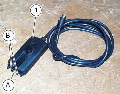
This operation, which is performed using the dds diagnosis instrument, has the advantage that it can be carried out on both timing belts with the engine still installed on the frame. The dds shall be connected with an optical reader (1) part no. 88765.1371. The optical reader has a green led that serves to determine that the reader is correctly positioned in front of the belt to be tested. It is also equipped with an infrared transmitter (a) and receiver (b) designed to detect oscillations of the belt when caused to vibrate with the flick of a finger.
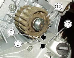
Position the crankshaft so that the piston of the horizontal cylinder is at tdc of its power stroke.
This is achieved by aligning the timing mark (c) of the timing driveshaft pulley (16) with the reference notch (d) on the clutch cover (17).
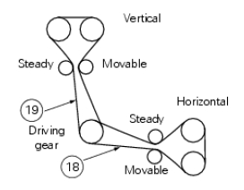
Measure the horizontal timing belt on the section (18) as described in paragraph "measuring the timing belt tension values".
Turn the crankshaft by 270 in the engine rotation direction (vertical cylinder tdc, in the combustion stroke) and repeat the procedure used for the horizontal cylinder, measuring the voltage on branch (19) of the vertical belt.
Remove the belt tension sensor and disconnect the dds diagnosis instrument from the motorcycle.
Measuring the timing belt tension values
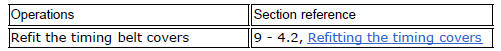
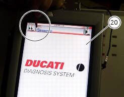
Switch on the dds (20) part no. 97900.0215 Referring to paragraph "tester power supply".
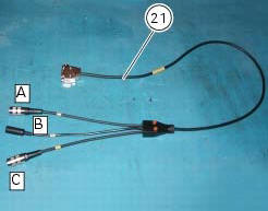
Connect the power and diagnosis cable (measurement module) (21) part no.97900.0222 To measurement module connector (f) of the dds (20).
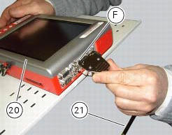
Connect the belt tension sensor (1) part no. 88765.1371 To the outlet (v) of the supply and diagnosis cable (measurement module) (21) part no. 97900.0222.
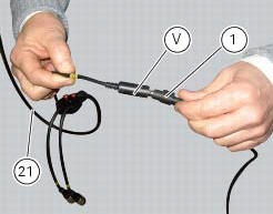
Fix the mounting bracket of the belt tension sensor (1) using the chain guard retaining screw (22).
Direct the central green led of the sensor (1) at the midpoint of the belt section, placing sensor (1) parallel to the belt and at a distance of about 1-1.5 Cm from it.
On the dds diagnosis instrument (20), select the "measurement module" function by pressing the corresponding icon; then press the "belt tension" icon followed by the "start" icon to access the "mechanical belt tension" screen.
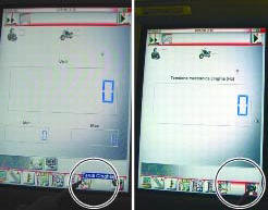
The socket to which the cable (measurement module) (21) is to be connected is indicated on the screen with a capital letter: a, b or c.
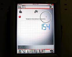
Flick the belt lightly with your finger and read the frequency value (hz) on the dds diagnosis instrument.
Note
Do not stress the belt several times repeatedly, since the necessary minimum time for the dds diagnosis instrument to take a reading is 1 second.
The tension values are those detailed in sect. 3 - 1.1, Timing system/valves and must be checked when the engine is cold: assembly values must be applied with when installing a new belt, while service values must be applied when belt tension reaches 70 hz.
Warning
The timing belts can become slack during normal operation. When checking belt tension, if the reading is less than 70 hz, retension the belt to restore the specified nominal values (sect. 3 - 1.1, Timing system/valves).
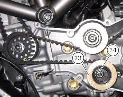
If the tension value is incorrect, increase or reduce belt tension, moving the adjustable tensioner pulley (23), loosening the nut (24): to tension the belt use the tool with part no. 88713.3497.
Tighten the nut (24) securing the tensioner pulley.
Recheck the timing belt tension.
Repeat the above procedure until the correct belt tension is obtained.
Once the belts are correctly tensioned, ensure that the fixing nut (24) of the tensioner pulley (23) is tightened to a torque of 25 nm (min. 22 Nm - max. 28 Nm) (sect. 3 - 3, Engine torque settings).
 Dds diagnosis instrument
The main functions of the dds diagnosis instrument can be summarised as
follows:
Retrieval of errors (faults) of the ignition-injection system stored in
the engine control unit memory and the ...
 Checking the idle speed
Check that the bike is provided with electronic control unit, oem intake and
exhaust systems, otherwise fit original
components.
Connect the inserts of the exhaust gas analyser code 88713.1010 T ...
Other materials:
Hands free key (hf) not recognised
The activation of this (amber yellow) "warning" indicates that the hands free
system does not detect the active key (1,
fig.62) Near the vehicle.
Note
Check that the active key (a) is near the vehicle (and has not been lost)
or that it works properly.
...
Trip 2 meter
This function shows the distance travelled since the trip
meter was last reset (in km or miles depending on the
specific application).
Holding the button (1, fig. 14) ?
pressed for 3 seconds
when this function is displayed resets the trip meter.
When the reading exceeds 9999.9, Distance t ...
General cleaning
To preserve the finish of metal parts and paintwork, wash
and clean your motorcycle at regular intervals, anyway
according to the road conditions you ride in. Use specific
products, where possible biodegradable. Avoid aggressive
detergents or solvents.
Use only water and neutral soap to clean ...