
Ducati Diavel Service Manual: Checking and overhauling the components
Clearance between the clutch drum and friction plates
Insert a friction plate (e) in the clutch drum (f) and measure the clearance (s) with a feeler gauge.
Clearance "s" must not exceed 0.6 Mm.
If it does, renew the plates and, if necessary, the clutch drum.
Overhaul of the clutch plates
The clutch plates must not show any signs of blackening, grooves or deformation.
Measure the thickness of the friction plates; it should not be less than 2.6 Mm.
Important
The total thickness of the discs pack must not be less than 46.1 Mm.
Place the plate on a flat surface and check the amount of deformation with a feeler gauge.
Max. Flatness error: 0.2 Mm.

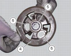
Overhaul of the pressure plate
Check bearing (5) condition; renew the bearing if the play is excessive.
Check the contact surfaces of the last friction plate; if extremely scored, polish it in the same manner as described previously for the cylinder head surface (sect. 9 - 4.5, Overhaul of cylinder head components).
Check conditions of the spring guide bucket tappet (g) of the pressure plate (4) and of the circlips (6).
Overhauling the pressure plate springs
Measure the length "l" of each spring (3).
Minimum length: 41 mm.
Renew any springs that are shorter than the above limit value.
 Removal of the clutch
Note
For clarity, the figures show the engine removed from the frame.
Undo the fixing screws (1) and remove the ring (2) and the springs (3) from
the pressure plate (4).
Slide the pre ...
 Reassembling the clutch
Position the spacer (13).
Fit the flat ring (11) and the belleville washer (10) on the clutch center
(12), so that the convex side faces the clutch
drum.
Locate the belleville washer (8). ...
Other materials:
Coverage
Warranty defects shall be remedied during customary
business hours at any authorized ducati motorcycle dealer
located within the united states of america in compliance
with the clean air act and applicable regulations of the
united states environmental protection agency and the
california air r ...
Lubricating cables and joints
Check the outer sheath of the throttle control and cold start
lever cables for damage at regular intervals. The outer plastic
cover should not be flattened or cracked. Operate the
controls to make sure the inner cables slide smoothly inside
the outer sheath: if you feel any friction or catching, ...
Removing of the rear footrests
The removal of the rear footrests is described for the right side but it is
the same for both.
Undo the pin (13) and remove the rh rear footrest (12) from the frame.
Recover washer (8) and the o-rings (9).
If necessary remove the rubber footrest (11) of the footrest (12).
...