
Ducati Diavel Service Manual: Checking protection and safety device components
Checking the side stand switch
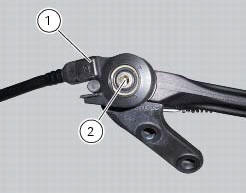
Remove the switch (1) from the side stand undoing screw (2) and disconnect the main wiring connector from the switch (see paragraph "routing of wiring on frame", sect. 6 - 1).
Use an analogue or digital multimeter (sect. 6 - 11, Using a multimeter to check the electrical systems) to check switch operation (see table).
Note
The same test may be carried out using the "dds" tester (sect. 6 - 11,
Diagnostic instruments). 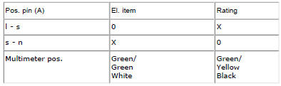
0 = Open contact
X = closed contact
Refit switch (1) to side stand and tighten the screw (2) to a torque of 5 nm +/-10 (sect. 3 - 3, Frame torque settings).

 Checking the fuses
The main fuse box (1) and the secondary one (2) are located in the tool tray;
to reach the fuse box remove the seat as
specified under sect. 5 - 3 "Removal of the seat".
The fuses are accessed b ...
Other materials:
Lcd unit functions
Speedometer.
Gives road speed.
Rev counter.
Indicates engine revs per minute.
Clock.
Water temperature indicator.
Indicates engine coolant temperature.
Important
Stop riding if the temperature reaches the maximum
value, otherwise the engine might be damaged.
...
Reassembly of rear shock absorber - rocker arm - linkage assembly
Once the needle roller bearings (9) have been removed from the rocker arm
(18), upon reassembly fit a new needle roller
bearing (9) on drift part no. 88713.1071 And lubricate with recommended grease.
Support the rocker arm and drive the needle roller bearings into the rocker arm
bore until t ...
Checking brake and clutch fluid level
The levels should not fall below the min marks on the
respective reservoirs.
If the level is too low, air can get into the circuit, thus
impairing the efficiency of the system.
Brake and clutch fluid must be topped up and changed at the
intervals specified in the scheduled maintenance table ...