
Ducati Diavel Service Manual: Checking the engine timing
Set the engine to the configuration described for the "checking and adjusting the valve clearances", previously indicated.
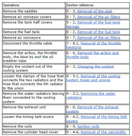
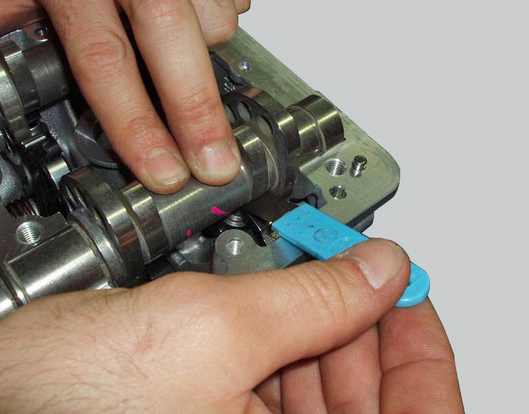
Install tool 88765.1188 (G) in the spark plug bore to determine the piston tdc, the gauges (h) on the tool 88765.1518 And the timing check tool (degree wheel (l) 88713.0123 With graduated disk).
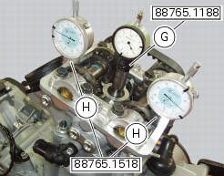

Set the opening valve clearance to zero when the camshaft is in its rest position by fitting a feeler gauge between the upper rocker arm and the opening shim.
Check that in this condition the camshaft can rotate. If it moves stiffly, use a thinner feeler gauge.
In this condition, with the piston of the horizontal cylinder at tdc with the valves fully closed as confirmed by the reading on gauge (g), set the gauges (h) to zero.
Set the tension value of the belts as described at sect. 6 - 11, Checking and adjusting timing belt tension.
Turn the degree wheel (l) counter clockwise until the gauge dial (h), on the exhaust side, shows a lift of 1 mm. Check that the value of the angular displacement read on the degree wheel (l) is as specified in (sect. 3 - 1.1, Timing system/valves).
Continue to rotate in the same direction until you obtain a lift of 1 mm on the intake side. Check the angular value on the degree wheel.
Continue to rotate until you obtain an intake valve lift of 1 mm on the gauge (h), during closure of the valve for the compression stroke. Check the angular value with the prescribed one (sect. 3 - 1.1, Timing system/valves).
Continue to rotate the degree wheel (l) counter clockwise until you obtain a lift of 1 mm of the exhaust valve, when opening or closing the valve.
Check the angular displacement value against the specified value.
Repeat the procedure for the vertical cylinder.
A tolerance of +/- 3 is allowed in the values detected with the described procedure regarding the prescribed ones (sect. 3 - 1.1, Timing system/valves).

Remove the installed tools to check timing. Then tension the belts to the value of the prescribed operation, as described at sect. 6 - 11, Measuring the timing belt tension values.
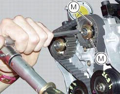
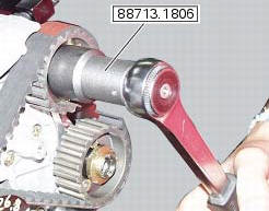
In case of values different from the described ones (sect. 3 - 1.1, Timing system/valves), loosen the fixing screws (m) of the timing pulley and correct the value detected by turning the ring nut of the timing shaft with the supplied wrench with code 88713.1806.
Lock the three retaining screws (m) of the timing pulley to the specified torque of 10 nm (min. 9 Nm - max. 11 Nm) (sect. 3 - 3, Engine torque settings) and mark the new position of the components.
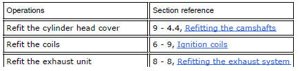
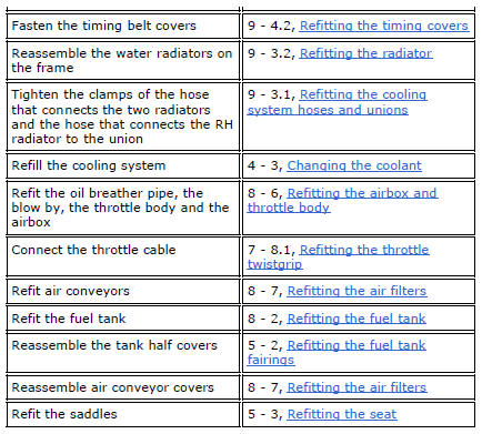
Refit the components removed in the procedure.
 Checking valve lift
Set the engine to the configuration described for the "checking and adjusting
the valve clearances", previously indicated.
Position the tool 88765.1518 On the cylinder head: the part marked "a" s ...
 Timing system
Central external cover
Air filter
Horizontal cylinder timing belt cover
Screw
Filter support
Screw
Washer
Nut
Tensioner pulley assembly
Circlip
Camshaft pulley
Tensioner p ...
Other materials:
Introduction to the "hands free" system
The hands free system allows the rider to start the engine without physically
using the ignition key. The ignition key
merely has to be in the vicinity of the motorcycle, such as in the rider's
pocket, for example, in order to use the vehicle.
Compared to the standard ignition switches the h ...
Overhauling the rear swingarm
Inside the swingarm (8), in correspondence with the pivot point on the frame,
there is a pair of ball bearings (10) and a
spacer (11) on the rh side, and a pair of roller bearings (6), with sealing
rings (5), on the lh side.
To change the bearings, proceed as follows.
Remove the shims ( ...
Topping up the electrolyte
Warning
Before carrying out any operations on the battery, keep in mind the
safety standards (sect.1 - 3, General safety rules).
The electrolyte in the battery is toxic and can cause burns if it comes into
contact with the skin because it contains
sulphuric acid. Wear protective clothing, a ...