
Ducati Diavel Service Manual: Checking valve clearances
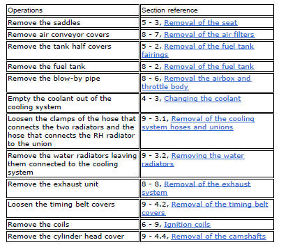
To check the valves clearance, it is necessary to have access to the cylinder head covers and then remove the components listed below.
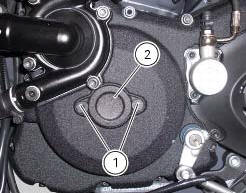
Unscrew the two fixing screws (1) of the cover (2) according to the crankshaft.
Fit the tool handgrip 88713.0123 In the holes of the generator cover to be able to turn the crankshaft so that the valve on which the control is carried out is in rest position.
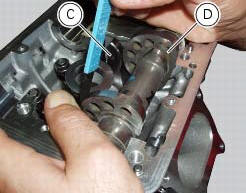
With the valve in the rest position, slide a feeler gauge between rocker arm (a) and the lowest side of the cam (b) to measure the clearance.
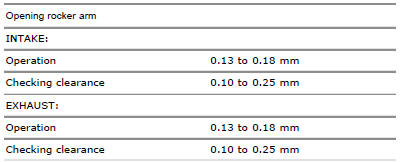
The clearances must be within the specified limits:
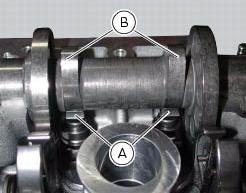

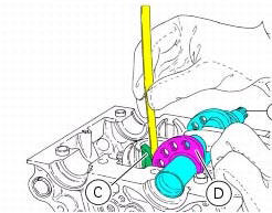
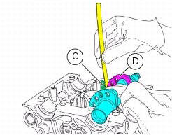
With the valve in the rest position, slide a feeler gauge between closing
rocker arm (c) and the highest side of the cam
(d) to measure the clearance. 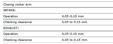
If detected values exceed the specified limits, replace opening and/or closing shims, as described in paragraph "removing the valves" (sect. 9 - 4.5), With an adequate height to obtain the specified clearance.
Note
Opening rocker arm shims measuring from 1.8 To 3.45 Mm and closing rocker arm shims measuring from 2.2 To 4.5 Are available as spare parts. The size is punched on the shim.
Remove the handgrip tool 88713.0123 From the hole of the generator cover.
Make sure that the o-ring (3) is fitted on the cover (2).
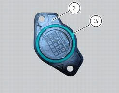
Refit the external cap (2) by tightening the two retaining screws (1) to a torque of 10 nm (min. 9 Nm - max. 11 Nm) (sect. 3 - 3, Engine torque settings).


Change timing belts
To replace the timing system belts follow the procedures described in paragraph "removal of the movable tensioner/timing belt" and "refitting the timing belts" (sect. 9 - 4.2).
 Changing the engine oil and filter cartridge
Note
This operation has to be carried out with hot engine (but turned off)
because the oil in these conditions is more fluid and
its evacuation is faster and complete.
Remove the drain plug (3) w ...
 Spark plugs replacement
Check the colour of the ceramic insulation around the central electrode:
an even, light brown colour indicates the engine is in good condition and
running at the right temperature.
Inspect the c ...
Other materials:
Replacing the front phonic wheel sensor
Disconnect the front abs sensor (2) connector (a) from the main electric
wiring.
Open all the retainer clamps of the front abs sensor cable (2): refer to table
of sect. 7 - 6, Flexible wiring/hoses
positioning.
Loosen retaining screw (1) and remove the front abs sensor (2) with
ca ...
Changing the clutch fluid
Warning
Clutch fluid will damage painted surfaces if spilled on them. It is
also very harmful if it comes into contact with the skin or
with the eyes; in the event of accidental contact wash the affected area with
abundant running water.
Remove cover (1) and membrane from the clutch fluid res ...
Indication of range reached for service
When service coupon threshold is achieved, upon every key-on the system
displays the indication of the type of
intervention that is required (oil service or desmo service).
The (red) warning is activated as a large icon for 10 seconds upon every key-on
(1) then as a small warning that
remai ...