
Ducati Diavel Service Manual: Checking valve lift
Set the engine to the configuration described for the "checking and adjusting the valve clearances", previously indicated.
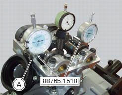
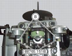
Position the tool 88765.1518 On the cylinder head: the part marked "a" should be on the intake side and the part marked "s" should be on the exhaust side.
Seat the plate (a) and tighten the screws (b).
Set the opening valve clearance to zero when the camshaft is in its rest position by fitting a feeler gauge between the upper rocker arm and the opening shim.
Lock the dial gauge into the seat of the stand marked "a" and position the fork probe against the face of the closing shim.
Set the dial gauge to zero when the valve is fully closed.
Rotate the intake camshaft so as to allow the intake valves to lift fully.
Check on the dial gauge that the measured value corresponds to the prescribed one (sect. 3 -1.1, Timing system/valves).
Repeat the same operation for the exhaust valves, using the dial gauge in the support seat 88765.1518 With the marking "s".
Refit the components by carrying out the same operations indicated in chapter "checking and adjusting the valve clearances", previously described.
Refit the components removed in the procedure.
 Checking and adjusting the valve clearances
Note
For clarity, the figures show the engine removed from the frame.
Move the piston of the cylinder being checked to tdc of the power stroke: in
this condition, all the valves are closed and ...
 Checking the engine timing
Set the engine to the configuration described for the "checking and adjusting
the valve clearances", previously indicated.
Install tool 88765.1188 (G) in the spark plug bore to determine the ...
Other materials:
Injectors
Introduction
The injectors used on the diavel are top feed units, meaning that fuel is fed
into the top of the injector itself. The
injectors contain a winding which raises a needle when electrically energised.
This opens the atomiser nozzle, through
which pressurised fuel is dispensed, gener ...
Refitting the hands free
Reassembly is a reversal of the removal procedure: in particular apply
prescribed threadlocker to screws (2) and tighten
them to a torque of 20 nm +/- 10% (sect. 3 - 3, Frame torque settings).
If the hands free button has been previously removed, when refitting it insert
the spring (6) on pi ...
Wiring diagram colour codes
B blue
Bk black
Bn brown
G green
Gr grey
Lb light blue
O orange
P pink
R red
V violet
W white
Y yellow
Rear left fuse box (1) key
Rear right fuse box (2) key
...