
Ducati Diavel Service Manual: Clock setting function
This function sets the clock.
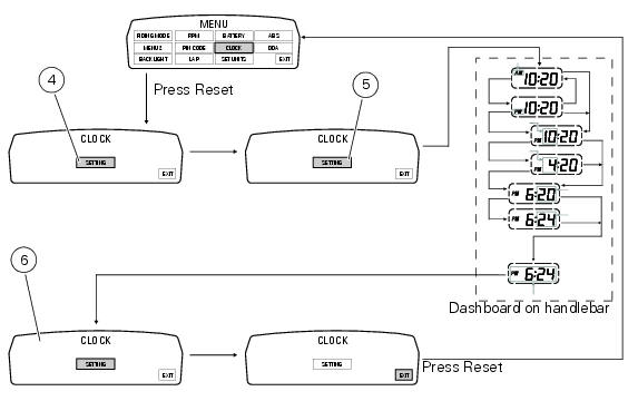
To access the function it is necessary to view the ""setting" menu", using buttons (1) "s" or (2) "t" select the "clock" function and press the reset button (3) to confirm.
In the following screen the message "setting" is highlighted in green (4); now, press the reset button (3) for 3 seconds to edit the time displayed on the handlebar dashboard, and the "setting" indication highlighting becomes grey (5).
Clock setting
On entering this mode, the message "am" will flash; press button (2) "t", the message "pm" starts flashing; press button (2) "t" to return to the previous step (if the current time is 00:00, 12:00 will be displayed when switching from "am" to "pm"); press button (1) "s" to access the hour setting mode; the hour value starts to flash; each time button (2) "t" is pressed increases the digit by 1 hour; pressing and holding button (2) "t", the digit increases by 1 hour every second (the hour value does not flash while the button is kept pressed).
Pressing button (1) "s" gives access to the minute setting mode; minutes start to flash.
Each time button (2) "t" is pressed increases the digit by 1 minute; pressing and holding button (2) "t", the digit increases by 1 minute each second; pressing and holding the button (2) "t" for more than 5 seconds, the value increases by 1 every 100 m (the second value does not flash while button (2) "t" is kept pressed).
If you press button (1) "s" setting is completed and the tank dashboard display "setting" item is again highlighted in green (6).
To exit, select "exit" and press the reset button (3).
Note
In case of a battery is cutoff, when the voltage is restored and at the next key-on, the clock is always reset (it starts automatically from 00:00).
 Battery voltage indicator (battery)
This function describes the battery voltage indicator.
To access the function it is necessary to view the ""setting" menu", using
buttons (1) "s" or (2) "t" select the "battery"
function and pre ...
 Units of measurement modification function
This function allows you to change the units of measurement of the displayed
values.
To access the function it is necessary to view the ""setting" menu", using
buttons (1) "s" or (2) "t" to sel ...
Other materials:
Removal of the gearbox assembly
Withdraw the selector fork shafts (30).
Move the forks (28) and (29) to disengage them from the slots in the selector
drum (14).
Withdraw the selector drum (16) taking care not to lose shims (31) and (27)
mounted on the shaft. Note that the
positions of the shims must not be inverte ...
How to use this manual
How to use this manual
This manual has been prepared for technical personnel at ducati authorized
service centres with the aim of providing
fundamental information on how to work in accordance with the modern concepts of
"best practice" and "safety in the
workplace" during the maintenance, re ...
Adjusting the position of the gear change and rear brake pedals
The position of the gear change and rear brake pedals in relation to the
footrests can be adjusted to suit the preferred
riding position.
To modify the gear change pedal position act in the following mode:
hold the linkage (1) and slacken the counter nuts (2) and (3).
Note
Nut (2) has a lef ...