
Ducati Diavel Service Manual: Coolant expansion tank
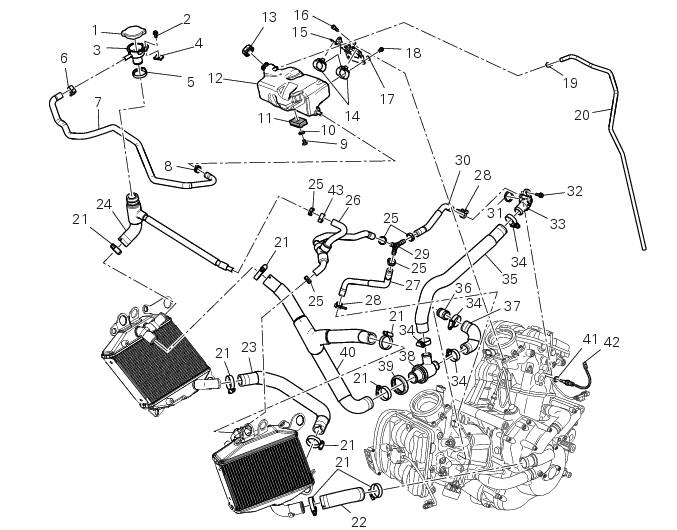
- Plug
- Screw
- Fuel filler flange
- Clip nut
- Clamp
- Hose clip
- Valve/tank hose
- Clamp
- Screw
- Spacer
- Rubber mounting
- Expansion reservoir
- Filler cap
- Hose clip
- Support
- Screw
- Washer
- Screw
- Hose clip
- Breather hose
- Clamp
- Pump/radiator sleeve
- Radiator/radiator sleeve
- Radiator/plug sleeve
- Clamp
- Breather pipe (front)
- Breather pipe (lower)
- Hose clip
- Y-fitting
- Breather pipe (rear)
- O-ring
- Screw
- Water outlet fitting (vertical)
- Clamp
- Thermostat/cylinder head sleeve (vertical)
- Fuel filler flange
- Thermostat/cylinder head sleeve (horizontal)
- Thermostat
- Thermostat protection ring
- Radiator/thermost. Sleeve
- Copper gasket
- Temperature sensor
- Clamp
Spare parts catalogue
Diavel abs cooling system
Diavel abs expansion reservoir
Diavel carbon abs cooling system
Diavel carbon abs expansion reservoir
Important
Bold reference numbers in this section identify parts not shown in the figures alongside the text, but which can be found in the exploded view diagram.
- Removal of the expansion tank
- Refitting the expansion tank
- Removal of the cooling system hoses and unions
- Refitting the cooling system hoses and unions
 Cooling system
...
 Removal of the expansion tank
Loosen the clamp (6), open the hose guide (a) and slide the hose (7) out of
the radiator.
Open clamps (14) and release the hoses that pass through them.
Loosen the screws (16).
Remove ...
Other materials:
Draining the clutch hydraulic circuit
Warning
Clutch fluid will damage painted surfaces if spilled on them. It is
also very harmful if it comes into contact with the skin or
with the eyes; in the case of accidental contact, wash the affected area
thoroughly with plenty of running water.
Remove the dust cap to expose the bleed val ...
Removal of the lubrication system
Disconnect the sensor (12) of the main wiring.
Open the pipe grommet (11).
Undo the screw (8) and slide out the plate (9).
Slide the tubes (7) out of the half-casing having care not to damage the tubes
o-rings (a) that guarantee the coupling
sealing.
Undo and remove the sc ...
Carrying the maximum load allowed
Your motorcycle is designed for travelling over long
distances with a full load in complete safety.
Even weight distribution is critical to preserving these safety
features and avoiding trouble when performing sudden
manoeuvres or riding on bumpy roads.
Warning
Do not exceed the total permi ...