
Ducati Diavel Service Manual: Coolant temperature
This function indicates coolant indication state.
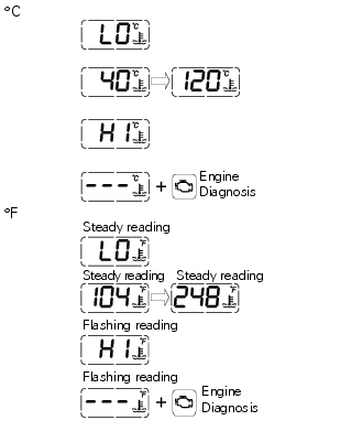
The temperature unit of measure can be selected (C or f).
The reading is indicated as follows: if the reading is between - 39C and +39C "lo" is shown flashing on the dashboard (steady); if the reading is between +40C and +120C it appears on the dashboard (steady); if reading is +121 C or higher, "hi" is shown flashing on the information panel.
Note
In the event of a sensor "error", flashing dashes ("- - -") are shown and the "engine/vehicle diagnosis - eobd" indicator turns on.
Display background colour (automatic adjustment)
Dashboard background colour is set automatically according to exterior lighting conditions.
When sensor detects "poor lighting" (night), it switches to black background mode; vice versa when a "significant" lighting is detected (day), it switches to white background mode. It is nevertheless possible to customise this function through the "setting" menu function "back light - dashboard 1", on page 62, and possibly set one of the two modes available, night or day, as permanent setting (or go back to auto mode).
 Clock
Clock
This function shows the time.
Time is always displayed as follows:
am from 0:00 to 11:59
Pm from 12:00 to 11:59
If battery power is suddenly cut off (batt-off), when battery power is
restored ...
 Dashboard on tank
Menu 1 (tot, trip1, trip2, trip fuel).
Menu 2 (cons.Avg., Cons., Speed avg, air and trip time) if active.
Gear / neutral indication.
Icon referred to the function below from menu 1.
Indicat ...
Other materials:
Ducati limited warranty on emission control system
Ducati north america, inc., 10443 Bandley drive cupertino,
california, 95014 warrants that each new 1998 and later
ducati motorcycle, that includes as standard equipment a
headlight, tail-light and stoplight, and is street legal:
a) is designed, built and equipped so as to conform at the
time o ...
Information about the model
Identification data
Diavel identification data
Each ducati motorcycle has two identification numbers -the frame number and
the engine number- and an ec nameplate
(a) (not present on the us version).
Note
Please quote these numbers, which identify the motorcycle model, when
ordering spare pa ...
Rear shock absorber assembly
Special screw
Screw
Nut
Grub screw
Bush (right)
Bush (left)
Screw
Sealing ring
Roller bearing
Linkage (left)
Shock absorber (rear)
Linkage (right)
Spacer
Special screw
Screw
Bush
Ball joint
Rocker arm assembly
Support
Washer
Nut
Screw
Shock absorber ...