
Ducati Diavel Service Manual: Cylinder/piston assemblies
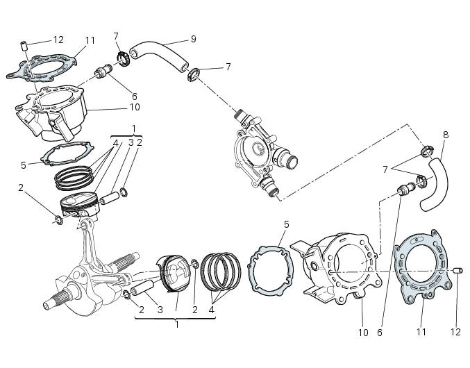
- Piston
- Gudgeon pin circlip
- Gudgeon pin
- Set of piston rings
- Cylinder-crankcase gasket
- Water pump outlet union
- Hose clip
- Horizontal cylinder coolant inlet hose
- Vertical cylinder coolant inlet hose
- Cylinder barrel
- Cylinder head gasket
- Bush
Spare parts catalogue
Diavel abs cylinders - pistons
Diavel carbon abs cylinders - pistons
Important
Bold reference numbers in this section identify parts not shown in the figures alongside the text, but which can be found in the exploded view diagram.
- Removal of the cylinder/piston assembly
- Overhaul of the cylinder barrel/piston components
- Refitting the cylinder/piston assembly
 Refitting the cylinder head assemblies
Warning
To prevent oil leaks past the contact area between cylinders and
crankcase, each time the head is removed, cylinder and
piston must be removed as well to clean the mating faces of crankcas ...
 Removal of the cylinder/piston assembly
Loosen the clamps (7) and remove the hoses (8) and (9) from the cylinder
barrels (10) and from the alternator-side
crankcase cover.
If damaged, unscrew the unions (6).
Note
T ...
Other materials:
Reassembling the frame and the lateral footrests
Apply the recommended grease to the thread of the pins (9) and of the nuts
(8).
Place the frame (1) and the brackets (2) and (3) on the engine block. Start the
pins (9) by holding the nuts (8) and insert
without tightening the screws (6) into the adjusters (4).
Position and fix the rear s ...
Clutch cover
Clutch-side crankcase cover
Screw
Screw
Oil level sight glass
Screw
Plate
Bush
Sealing ring
Shim washer
Circlip
O-ring
Locating bush
O-ring
Plug
Sealing washer
Screw
Plug
Panel
Spare parts catalogue
Diavel abs clutch-side crankcase cover
Diavel carbon
a ...
Reassembling the electrical components support
Check the presence of clips (1), (9) and (24) on the support (5).
Check the presence of rubber pads (6) and (8) and of cable grommet (7).
Check that the voltage regulator (3) and the solenoid starter (18) are in
place on the support (5) with their wiring as
shown.
The horn (22) mus ...