
Ducati Diavel Service Manual: Description of the diagnosis instrument (dds)
The "dds" diagnostic system lets you diagnose any faults in the injection-ignition system via a serial port. The system is also equipped with functions to test various devices on the motorcycle. The dds diagnosis instrument can be used to measure current and voltage on any electrical device, to perform tests on individual components and to measure pressure and temperature values.
The dds (1) part number 97900.0215 Consists of a palmtop display (a), a bbad self-diagnosis module (b) and a display memory card (c).
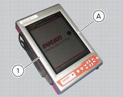
The touch-screen display unit (a) serves for both data display and input, using the stylus housed on the side of the unit.
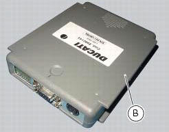
The self-diagnosis module (b) enables communication between the dds diagnosis instrument (1) and the motorcycle’s on-board electronic control unit (ecu).
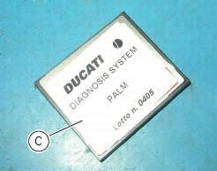
The user interface software resides in the display memory card (c) which is housed in the palmtop display unit (a).
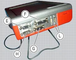
The display unit is equipped with two connection panels: one at the top of the instrument and one at the bottom.
The top connection panel has 6 connection sockets with the following functions:
- One vga output (e);
- One port for connection of the measurement module (f);
- One rs232 serial port for connection of peripheral devices (com1) (g);
- A second rs232 serial port for connection of peripheral devices (com2) (h);
- Two generic usb ports (usb1 and usb2) (l).
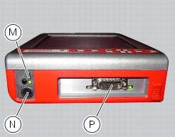
The bottom connection panel has 3 connection sockets with the following functions:
- One usb port (m);
- One power connection socket (n);
- One diagnostics connection socket (p).
You can connect a printer to the dds diagnosis instrument (1) to print test reports: connect the printer to the serial port (com1) (g) located on the top connection panel of the tester (1).
Technical data
Power supply:
- From the mains - 220 v;
- From the vehicle battery - 12 v.
Components supplied with the dds diagnosis instrument
The dds diagnosis instrument (1) is supplied in a kit together with the following items:
- Rechargeable dds battery
- Battery charger
- Mains power adapter
- Usb memory card reader
- Power and diagnostic cable complete with fuse
- Cd containing dds installation software for pc
- Usb cable
- Belt tension sensor
 Using a multimeter to check the electrical systems
Introduction
This instrument allows you to measure resistance, voltages, and current
values. Multimeters can be divided into two basic
types: analogue and digital display multimeter. An analogue m ...
 Tester power supply
The dds (1) part number 97900.0215 Can be powered from the vehicle as
follows:
From the mains power supply: by connecting the power supply connector
(n) to the network power supply (2) pa ...
Other materials:
Refitting the seat
Note
Apply recommended grease to the hole (a) of latch (6).
Fit the seat (1) as follows: insert the tabs (b) (on the front side) under
the rubber pads (c) of the gloves compartment;
then push the seat rear side until hearing the lock latch click.
...
Removal of the front footrests
Note
The removal of the front footrests is described only for the right one (2)
but it is the same also for the left one.
Remove the circlip (5) by releasing the pin (3).
Slide the pin (3) off the frame by supporting the footrest (2).
Slide off the footrest (2) from its seat and collect th ...
Adjusting the rear shock absorber
The rear shock absorber has external commands that enable
you to adjust the setting to suit the load on the motorcycle.
The adjuster (1, fig. 111) Located on the lower connection
holding the shock absorber to the swingarm adjusts the
damping during the rebound phase (return).
The knob (2, f ...