
Ducati Diavel Service Manual: Disassembly of structural components and the frame
Before carrying out dimensional checks on the frame, you must remove all the superstructures fitted, referring to the removal procedures outlined in the sections of this manual.
The rear subframes (2) and (3) are structural components of the frame (1).
Both serve to support motorcycle superstructures and must therefore be in perfect condition.
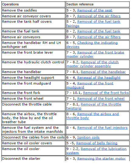
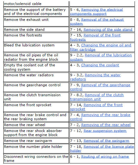
The following flow chart illustrates the logical sequence in which the parts are to be removed from the motorcycle and a reference to the section where the removal procedure is described.
Refitting is the reverse of removal.
 Frame inspection
Frame
Rh subframe
Lh subframe
Grub screw
Nut
Special screw
Rubber pad
Nut
Special screw
Screw
Left-hand bracket
Hose clip
Hose clip
Right-hand bracket
Special screw
...
 Removal of the tool tray
To remove the tool tray unit from the lateral footrests, loosen the screws
(40) and remove the splashguard (20).
Undo the screws (15) and remove the cover (16).
Move the wiring branch ...
Other materials:
Refitting the rear wheel
Lubricate the wheel shaft threaded end with prescribed grease.
Insert the wheel shaft by matching (a) with pins (b).
Install spacer (3) with the conical surface faced to the wheel conical
surface, washer (2), apply prescribed grease to nut
(1) and insert it by hand (1).
Tighten the ...
Trip 1 meter
This function shows the distance travelled since the trip meter was last
reset (in km or miles depending on the specific
application).
Press and hold (1) "s" for 3 seconds while in this function to reset the trip
odometer.
When the reading exceeds 9999.9, Distance travelled is reset and t ...
Injection relay
Introduction
The fuel pump, injectors and ignition coils are all powered via the injection
relay. The relay also sends voltage to the
engine control unit, which enables activation of the relay itself.
Component assembling position
A injection relay; b etv relay (throttle valve actuator mot ...