
Ducati Diavel Service Manual: Disassembly of the gearbox shafts
Place the shaft in a vice in such a way as to facilitate the disassembly operations.
Important
Take care not to invert the positions of the shims on reassembly: this would potentially lead to jamming when using the gear selector control, making it necessary to reopen the engine crankcase.
Disassembly of the gearbox secondary shaft
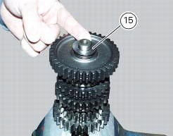
Remove the chain-side shim washer (26) and clutch-side shim washer (15) from the secondary shaft.
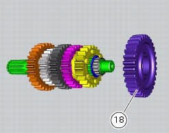
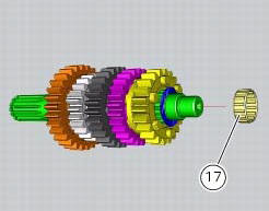
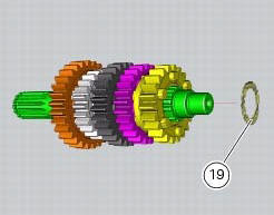
Withdraw the first speed driven gear (18) with the roller cage (17) and the shim (19).
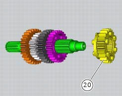
Remove the fifth speed driven gear (20).
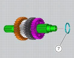
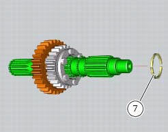
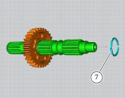
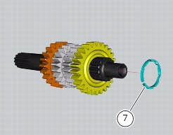
Use two flat blade screwdrivers to remove the circlip (7) taking care not to damage the shaft surface.
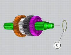
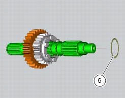
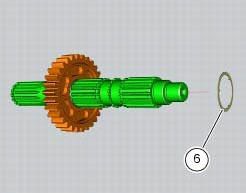
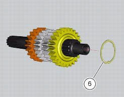
Remove the circlip (7) and the splined washer (6).
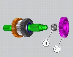
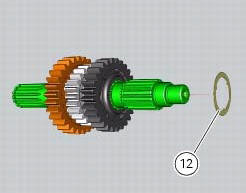
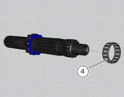
Withdraw the fourth speed driven gear (21) with the roller cage (4) and splined washer (12).
Remove the
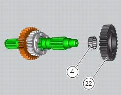
Remove the third speed driven gear (22) with the roller cage (4) and the splined washer (6).
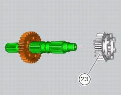
Remove the circlip (7) and remove the sixth speed driven gear (23).
Remove
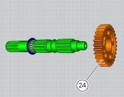
Remove the circlip (7) and withdraw the splined washer (6) and the second speed driven gear (24).
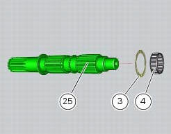
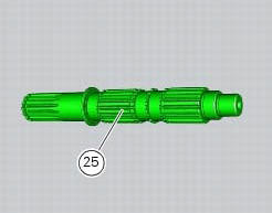
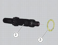
Withdraw the roller cage (4) and the shim (3). All the components have thus been removed from gearbox secondary shaft (25).
Disassembly of the gearbox primary shaft
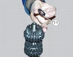
Remove the chain-side shim washer (11) and the clutch-side shim washer (1) from the primary shaft.
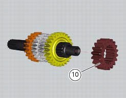
Remove the second speed driving gear (10). Use two screwdrivers to prise out the circlip (7) and the splined washer (6).
Important
Take care to avoid damaging the surface of the shaft while removing circlip (7).
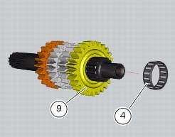
Remove the sixth speed driving gear (9) with its roller cage (4). Remove the splined washer (6) and the circlip (7).

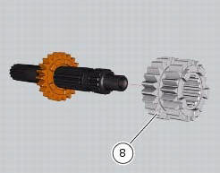
Withdraw the third and fourth speed driving gear (8).
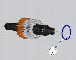
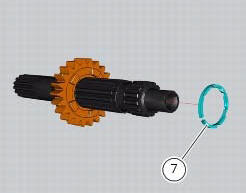
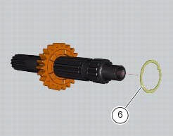
Remove the circlip (7) and the splined washer (6).
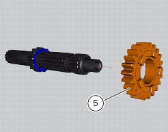
Remove the fifth speed driving gear (5) with the roller cage (4).
Slide the shim (3) off the primary shaft (2).
 Removal of the gearbox assembly
Withdraw the selector fork shafts (30).
Move the forks (28) and (29) to disengage them from the slots in the selector
drum (14).
Withdraw the selector drum (16) taking care not to lose s ...
 Overhaul of the gearbox
Check the condition of the front coupling dogs of the gears. They must be in
perfect condition and with no sign of wear on
the edges of the teeth.
The idler gears must rotate freely on their sha ...
Other materials:
Lubricating cables and joints
Check the outer sheath of the throttle control and cold start
lever cables for damage at regular intervals. The outer plastic
cover should not be flattened or cracked. Operate the
controls to make sure the inner cables slide smoothly inside
the outer sheath: if you feel any friction or catching, ...
Removal of the brake discs
The front brake discs consist of an inner carrier, which is mounted to the
wheel, and an outer rotor. Both parts must be
changed together as a pair.
Remove the front wheel (sect. 7 - 1, Removal of the front wheel).
Undo the retaining screws (5) of the disc to the wheel, remove the disc (7) ...
Carrying the maximum load allowed
Your motorcycle is designed for travelling over long
distances with a full load in complete safety.
Even weight distribution is critical to preserving these safety
features and avoiding trouble when performing sudden
manoeuvres or riding on bumpy roads.
Warning
Do not exceed the total permi ...