
Ducati Diavel Service Manual: Disassembly of the generator cover
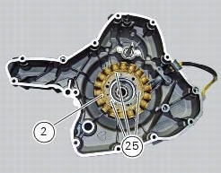
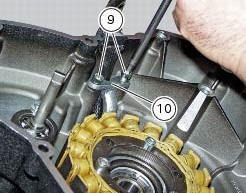
Undo the three stator retaining screws (25) and the two retaining screws (9) of the two cable grommet bracket (10) from inside the generator cover.
Remove the stator (2) and the cable grommet bracket (10).
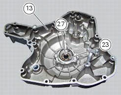
The generator-side crankcase cover is fitted with a bearing (27), held in place by circlip (23), which is located on the end of the crankshaft.
Remove the circlip (23) with circlip pliers.
Remove the bearing (27) using a universal puller.
Be careful when fitting the new bearing (27) to ensure it is positioned with the shielded side facing away from the cover.
Secure the bearing with the circlip (23), ensuring that it is correctly fitted in its seat in the generator cover (13).
Remove the water pump components as described in sect. 9 - 3.3, Removal of the water pump.
 Removal of the generator cover
Note
This operation is described for an engine removed from the frame since all
reassembly procedures are easier with the
engine on the bench.
Disconnect the connector (a) from the generator ...
 Removing the flywheel - generator assembly
Use the tool 88713.3367 Fixed to the m10 side stand fixing holes (d).
Secure the tool to the flywheel with the screws (e).
Unscrew the alternator-flywheel retaining nut (15).
Warning
While uns ...
Other materials:
Checking protection and safety device components
Checking the side stand switch
Remove the switch (1) from the side stand undoing screw (2) and disconnect
the main wiring connector from the switch
(see paragraph "routing of wiring on frame", sect. 6 - 1).
Use an analogue or digital multimeter (sect. 6 - 11, Using a multimeter to check
the ...
Engine torque settings
*Dynamic safety-critical point; tightening torque must be within nm +/-5%.
Note
For product specifications and symbols, refer to paragraph "product
specifications" (sect. 1 - 2). ...
Key-on/key-off using the key on the hands free lock with the passive key
Key-on can be performed by pressing the button (7) on the
hands free lock and with the presence of the passive key (4,
fig. 77).
Note
The passive key (4, fig. 77) Has a range of a few cm,
therefore the key (4, fig. 77) Must be positioned near the
antenna (2). Remove the seat (see "remova ...