
Ducati Diavel Service Manual: Disassembly of the rear brake control
The brake master cylinder is supplied only as a complete unit; internal components cannot be replaced.
To disassemble the master cylinder's outer parts, follow the indications given in the exploded view at the beginning of this section.
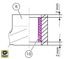
If the bush (10) inside the brake pedal (6) needs to be replaced, grease the external surface and fit the new bush using a press to insert it. The bush must be placed at 2 mm from the pedal external face.
To disassemble the various parts of the system, refer to the exploded view at the beginning of this chapter.
Warning
After performing an operation on the rear brake control, check the brake pedal position following the instructions detailed in sect. 4 - 3, Adjusting the position of the gear change and rear brake pedals.
 Removing of the rear brake control
Warning
The brake master cylinder manufacturer advises against servicing the
brake master cylinder due to the safety critical
nature of this component.
Incorrect overhaul can endanger the rider ...
 Refitting the rear brake control
If the pushrod (18), clip (30) and fork (31) assembly has been dismantled,
reassemble it by screwing the nut (29) onto
the rod (18) and then screw the rod into the fork (31) to obtain the measureme ...
Other materials:
Checking drive chain tension
Important
Have chain tension adjusted by a ducati dealer or
authorised service centre.
Make the rear wheel turn until you find the position where
chain is tightest.
Set the vehicle on the side stand. Push down the chain at the
point of measurement and release.
Measure the distance betwee ...
Adjusting the rear shock absorber
The rear shock absorber has external commands that enable
you to adjust the setting to suit the load on the motorcycle.
The adjuster (1, fig. 111) Located on the lower connection
holding the shock absorber to the swingarm adjusts the
damping during the rebound phase (return).
The knob (2, f ...
Final drive
Circlip
Nut
Washer
Nut
Rear sprocket flange
Cush drive bush
Inner ring
Chain
Spacer
Chain cover
Screw
Nut
Lock washer
Front sprocket
Spacer
O-ring
Rear sprocket
Spare parts catalogue
Diavel abs gearbox
Diavel abs rear wheel axle
Diavel carbon
abs
gearbo ...