
Ducati Diavel Service Manual: Draining the clutch hydraulic circuit
Warning
Clutch fluid will damage painted surfaces if spilled on them. It is also very harmful if it comes into contact with the skin or with the eyes; in the case of accidental contact, wash the affected area thoroughly with plenty of running water.
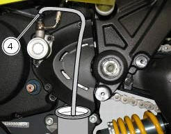
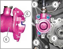
Remove the dust cap to expose the bleed valve (4).
Connect a clutch circuit bleeding tool to the clutch transmission unit bleed valve (4).
Note
Follow the manufacturer's instructions when using a commercial clutch bleeding tool.
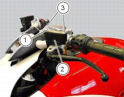
Remove cover (1) and membrane from the clutch fluid reservoir (2) by loosening the screws (3).
Open the bleed valve and pump with the bleeding tool until no more fluid emerges.
If you do not have a bleeding tool available, attach a length of transparent plastic tubing to the bleed valve (4) and insert the other end of the tubing in a container of old clutch fluid placed on the floor.
Unscrew the bleed valve by a 1/4 turn.
Operate the clutch lever until all the fluid has been expelled.
To completely empty the circuit it is advisable to remove the cap of clutch recover.
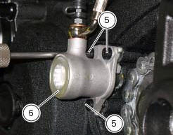
Undo the screws (5) and slide out the clutch slave cylinder (6).
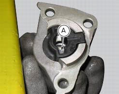
Push in the internal piston (a) to force out all the fluid from inside the cap.
Make sure the anti-rotation pin (8) is fitted on the clutch pushrod (7).
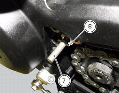
Proceed as follows in case the anti-rotation pin (8) has been removed from the clutch pushrod (7).
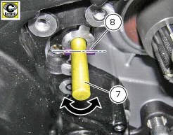
Turn the clutch pushrod (7) until the axis of the anti-rotation pin (8) positioning hole is horizontal, as shown in the figure; grease the anti-rotation pin (8) and insert it into the clutch pushrod (7) hole.
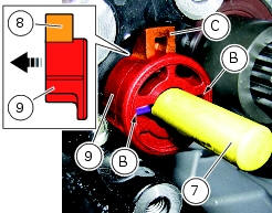
Insert the anti-rotation insert (9) fully home into the clutch pushrod (7) by matching the anti-rotation pin (8) with the slots (b) on the insert (9).
Note
The tab (c) of insert (9) must be inwards (casing side).
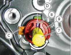
Turn the clutch pushrod (7) counter clockwise until the hole axis of the anti-rotation pin (8) is aligned with the centreline of the casing cover machined surface (d), as shown in the figure.
Insert the clutch actuator (6) into the pushrod (7) and bring it fully home on the anti-rotation insert (9).
Note
Upon insertion of the clutch actuator (6), make sure that the tab (c) of insert (9) matches with the actuator slot (e).
Fix the clutch actuator (6) by starting the screws (5).
Note
To bring the clutch slave cylinder (6) internal surface near the casing cover as uniformly as possible, screw and tighten the screws (5) alternatively.
Tighten the screws (5) to a torque of 10 nm +/- 10% (sect. 3 - 3, Frame torque settings), by following the sequence 1 - 2 - 3 - 1.
Tighten the screw (4) to a torque of 23 nm +/- 10% (sect. 3 - 3, Frame torque settings).
 Changing the clutch fluid
Warning
Clutch fluid will damage painted surfaces if spilled on them. It is
also very harmful if it comes into contact with the skin or
with the eyes; in the event of accidental contact wash the a ...
 Filling the clutch circuit
Warning
Clutch fluid will damage painted surfaces if spilled on them. It is
also very harmful if it comes into contact with the skin or
with the eyes; in the case of accidental contact, wash the a ...
Other materials:
Oxygen sensors
Introduction
An on-off type oxygen sensor (in normal operating conditions, the voltage
generated by the sensors switches between a
value close to 1v and a value close to 0v) is mounted on each of the exhaust
manifold of the diavel.
Each oxygen sensor has its own internal heater, which recei ...
Immobilizer override procedure
This procedure makes it possible to "temporarily" turn on the motorcycle if
the hf (hands free) system is not working.
Note
The pin code function must be activated by entering your 4 digit pin in
the dashboard, otherwise the vehicle cannot be
turned on temporarily in the case of a malfunction ...
Removal of the exhaust system
Remove the silencer, as described in the paragraph "removing the silencer" of
this section.
Loosen the screws (28) and remove the exhaust by-pass valve cover (27).
Turn the exhaust valve pulley (a) to facilitate the throttle cable (25)
output.
Release the end fitting (b) of the cable ...