
Ducati Diavel Service Manual: Dtc (ducati traction control) setting function
This function allows you to customise the level of dtc intervention (ducati traction control) or disable it for every riding mode.
To access the function it is necessary to view the ""setting" menu", using buttons (1) "s" or (2) "t" select the "riding mode" function and press the reset button (3) to enter the following page. Use button (1) "s" or (2) "s" to select the riding style to change and press the reset button (3).
To go to next page use button (1) "s" or (2) "s" to select the "dtc" indication and press the reset button again (3) to confirm selection.
When accessing the function, the currently set dtc level appears at the left-hand side of the display, inside a rectangle (ex.: Dtc 1). Use button (1) "s" or (2) "s" to select the new intervention level (1 to 8) or off to disable the traction control; after selecting the new setting, press the reset button (3) to highlight "memory" indication. At this point, store the new setting by pressing and holding the reset button (3) for 3 seconds with "memory" displayed. If the setting has been stored successfully, the display will show "memorized" in green for 2 seconds and the exit option will be highlighted automatically.
To exit the setting function, press the reset button (3) when "exit" is highlighted.
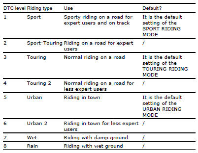
The dtc intervention increases, passing from level 1 to level 8.
The following table indicates the most suitable level of dtc intervention for
the various riding types as well as the default
settings in the "riding mode" that can be selected by the rider:
 Riding mode customisation
This function customises each riding style.
To access the function it is necessary to view the ""setting" menu", using
buttons (1) "s" or (2) "t" select the "riding
mode" function and press the ...
 Tips on how to select the sensitivity level
Warning
The 8 level settings of the dtc were calibrated using tyres of the
same make, model and size as those originally fitted to
the motorcycle.
The use of tyres of different size to the orig ...
Other materials:
Overhaul of the flywheel-alternator assembly
Examine the inner part of alternator rotor (24) for signs of damage. Check
that the starter clutch is working properly and
that the needle races do not show signs of wear or damage of any kind. If there
is any malfunction, remove the whole
assembly.
Disassembling the generator flywheel
U ...
Checking the frame
Check the dimensions of the frame against the dimensions shown here to
determine whether it needs to be realigned or
renewed.
Important
Damaged frames must be changed, not repaired. Any work carried out on the
frame can give rise to potential danger,
infringing the requirements of ec directi ...
Removing of the cylinder head pulley/fixed tensioner
Insert the tool code 88713.1806 In the pulleys to lock their rotation and use
the bush supplied to loosen the fixing nuts
(21) of the pulleys.
important
On reassembly, always use new nuts.
Remove the nuts (21) and the pulleys (11) from the camshafts.
Loosen the nut (8), and remove the was ...