
Ducati Diavel Owners Manual: Dtc (ducati traction control) setting function
This function allows you to customise the level of dtc intervention (ducati traction control) or disable it for every riding mode.
To access the function it is necessary to view the "setting" menu page 48, using
button (1, fig. 14) ?" " or (2, fig.
14) ?"  " select the "riding mode"
function and press the reset button (12, fig. 12) To go to next page. Use button
(1, fig. 14) ?" " or (2, fig. 14) ?"
 "
"
to select the riding style to
change and press the reset button (12, fig. 12).
To go to next page use button (1, fig. 14) ?" "
"
or (2, fig. 14) ?" " to select the "dtc" indication
and press the reset
button again (12, fig. 12) To confirm selection.
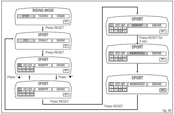
When accessing the function, the currently set dtc level appears at the
left-hand side of the display, inside a rectangle (ex.: Dtc 1). Use button (1,
fig. 14) ?" " or (2, fig. 14) ?"
 " to
" to
select the new intervention level (1 to 8) or off to disable
the traction control; after selecting the new setting, press
the reset button (12, fig. 12) To highlight "memory"
indication. At this point, store the new setting by pressing
and holding the reset button (12, fig. 12) For 3 seconds with
"memory" displayed. If the setting has been stored
successfully, the display will show "memorized" in green
for 2 seconds and the exit option will be highlighted
automatically.
To exit the setting function, press the reset button (12, fig.
12) Where "exit" is highlighted.
The dtc intervention increases, passing from level 1 to level 8.
The following table indicates the most suitable level of dtc
intervention for the various riding types as well as the default
settings in the "riding mode" that can be selected by the
rider: 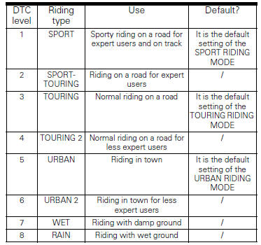
 Riding mode customisation
This function customises each riding style.
To access the function it is necessary to view the "setting"
menu page 48, using button (1, fig. 14) ?
or (2, fig. 14)
? select the & ...
 Tips on how to select the sensitivity level
Warning
The 8 level settings of the dtc were calibrated using
tyres of the same make, model and size as those originally
fitted to the motorcycle.
The use of tyres of different size to the orig ...
Other materials:
Disassembly of the gearbox shafts
Place the shaft in a vice in such a way as to facilitate the disassembly
operations.
Important
Take care not to invert the positions of the shims on reassembly:
this would potentially lead to jamming when using the gear selector control,
making it necessary to reopen the engine
crankcase.
D ...
Swingarm
Swingarm pivot
Washer
Special screw
Bush
Sealing ring
Roller bearing
Special screw
Rear swingarm
Spacer
Bearing
Spacer
Spacer
Hose clip
Pin
Chain slider (lower)
Washer
O-ring
Calliper mounting bracket
Circlip
Spacer
Inner ring
Hub
Cable grommet
Ch ...
Checking drive chain tension
Important
Have chain tension adjusted by a ducati dealer or
authorised service centre.
Make the rear wheel turn until you find the position where
chain is tightest.
Set the vehicle on the side stand. Push down the chain at the
point of measurement and release.
Measure the distance betwee ...