
Ducati Diavel Service Manual: Electrical power for lighting and signalling devices
The front and rear running lights consist of led units with light conduits. As a result, the light source is not visible as the light is diffused through the surface of the light conduit.
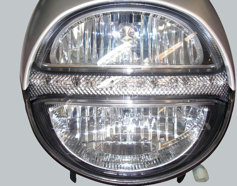
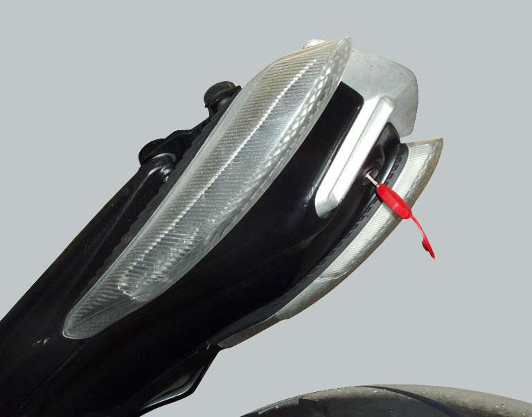
These two images illustrate the front and rear running lights with light conduits.
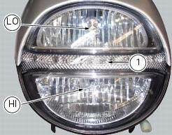
The figure shows the locations of the low beam bulbs (lo), high beam bulbs (hi) and the parking light led light unit (1).
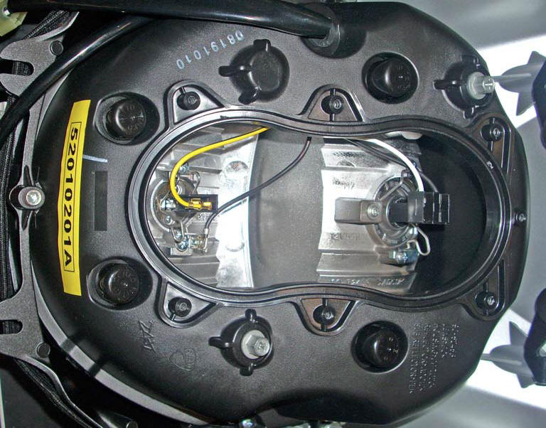
Rear view of the headlight showing the high and low beam light connections and the connection for the led power module at the centre, with the connector cable.
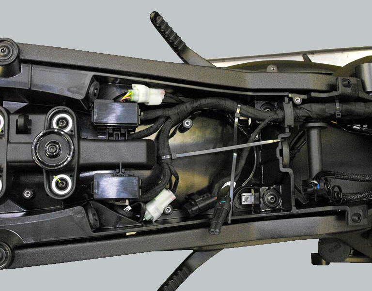
To access the tail light - turn indicators unit, remove the seat as described in sect. 5 - 3, "Removal of the seat" and the tool tray cover as described in sect. 7-17, "Removal of the tool tray".
The bbs and the dash board unit provide electric power to the lighting and signal devices, which therefore have no conventional power supply passing via a fuse and no electric switchgear set on the handlebar. Commands for the lights and signals are in fact sent to the control units, which then activate the relative lighting devices. The following table indicates the types of devices used, the type of power supply and whether or not the devices are testable.
| Device type | Power type | Function |
| Front led turn indicators, commanded directly from dash board | Pwm without specific fuse | Not testable |
| Rear turn indicators with incandescent bulbs, commanded directly from bbs | 12V without specific fuse | Bulb function may be tested |
| Number plate light with incandescent bulb commanded directly from dash board | Pwm without specific fuse | bulb function may be tested |
| Low beam lights with incandescent bulbs | 12V with fuse | Bulb pwm |
| High beam lights with incandescent bulbs | 12V with fuse | Bulb function may be tested |
| Front and rear led running lights, commanded directly from bbs | 12V without specific fuse | Device function may be tested using an external 12v power source |
| Led stop light, commanded directly From bbs | 12V without specific fuse | Device function may be tested using an External 12v power source |
As soon as you start the engine the low beam turns on automatically. In key-on condition and engine off it is possible to turn on the high and low beams that will switch off after 60 seconds if the engine is not started: in key-on condition the headlights are off, in key-on and engine running the headlights turn on automatically and in key-on it is possible to turn them on with the lh switch.
 Ground connection locations
The negative cable, which is normally connected to the negative pole of the
battery, is fastened to the crankcase. From here, the cable
branches off and splits up within the electrical system to ca ...
 Location of elements on motorcycle
(A) injection relay; (b) etv relay (throttle valve operating engine); (c)
radiator fan relay; (d) hands free relay.
(E) ecu; (g) bbs (black box system or central electronics); (f) abs h ...
Other materials:
Specific operating strategies
Idle speed
No electric motor is used for idle speed regulation (bypass is modulated
instead with the throttle valve), as idle speed
control is effected by the ride-by-wire system. Idle speed is maintained by the
control unit when the speed drops below a
specific threshold and when the clutch ...
Adjusting the steering head bearings
Note
To adjust the steering bearing clearance, follow what is described in
sect. 4 - 3, Adjusting the steering head bearings.
If the problems found are not solved, check the wear of steering bearings (6)
and replace them, if necessary, as described
in paragraph "removal of the steering head c ...
California emission control warranty statement
Your warranty rights and obligations
The california air resources board is pleased to explain the
emission control system warranty on your my 2011
motorcycle. In california, new motor vehicles must be
designated, built and equipped to meet the state's stringent
anti-smog standards. Ducati north ...