
Ducati Diavel Owners Manual: Engine on/off
 Warning
Before starting the engine, become familiar with the controls you will need to use when riding (page 99).
 Warning
Never start or run the engine indoors. Exhaust gases are toxic and may lead to loss of consciousness or even death within a short time.
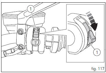
In the presence of the active or passive key, perform a key- on (turning on the "hands free" system and all on-board electronic devices) by pushing the red switch (1, fig. 117), On the right side of the handlebar, downward.
The instrument panel on handlebar will perform the initialisation and will control the onboard systems, turning on all lights in sequence, from outside to inside, for a few seconds.
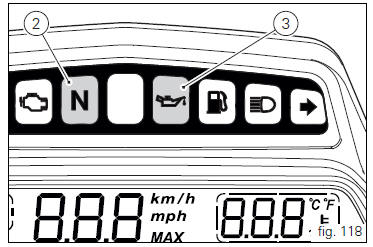
After this control, only the green light (2, fig. 118) And the red
light  (3) must remain on.
 Warning
The side stand must be fully up (in a horizontal position) as its safety sensor prevents engine start when down.
After key-on, but with the engine not yet started, the system will perform a key-off automatically if the presence of the active key is not detected within 10 seconds.
 Note
Note
It is possible to start the engine with side stand down and the gearbox in neutral. When starting the bike with a gear engaged, pull the clutch lever (in this case the side stand must be up).
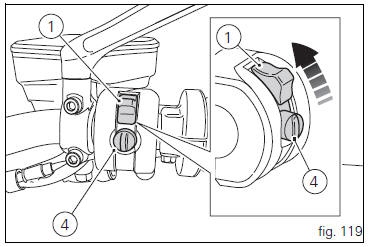
Move the red switch (1) up to uncover the black button (4, fig. 119).
Push the button (4) to start the engine.
 Important
Do not rev up the engine when it is cold. Allow some time for the oil to warm up and reach all points that need lubricating.
The red oil pressure warning light should go out a few seconds after the engine has started.
The engine will shut off by turning the red key (1, fig. 119) On the handlebar to run off.
 Note
Note
To turn on the "hands free" system and all electronic onboard systems, refer to page 100 "hands free system".
 Pre-ride checks
Warning
failure to carry out these checks before riding, may
lead to motorcycle damage and injury to rider and passenger.
Before riding, perform a thorough check-up on your bike as
follows:
Fuel ...
 Moving off
Disengage the clutch by squeezing the clutch lever.
Push down the gear change lever firmly with the tip of
your foot to engage first gear.
Raise the engine revs by turning the throttle twistg ...
Other materials:
Removing the front footrest brackets
Note
The assembly of the front footrests is described only for the right one
(2) but it is the same also for the left one.
Place the spring (4) bringing the end (a) onto the footrest (2).
Place the footrest (2) in the correct position, by inserting the end (c) of the
spring (4) in the hole ...
Low beam lights not working
Location of connections and components
(A) injection relay; (b) etv relay (throttle valve operating engine); (c)
radiator fan relay; (d) hands free relay.
Fuses located at the rear left of the vehicle.
(1) 10A dashboard; (2) 5a engine control unit; (3) 15a key-sense; (4) 20a
injecti ...
Adjusting the front fork
The front fork used on this motorcycle has rebound, compression and spring
preload adjustment.
This adjustment is done using the outer adjusters:
Rebound damping;
Inner spring preload;
Compression damping.
Park the motorcycle in a stable position on its side stand.
Turn the adjust ...