
Ducati Diavel Service Manual: Exhaust by-pass valve not working correctly
Fault codes
Dds: exvl diagnosis -> position error, potentiometer, short circuit to ground or open circuit (s.C. Gnd or c.O.), Potentiometer short circuited to vdc (potentiometer s.C vdc).
Dashboard: the error "exvl" (exhaust bypass valve) is shown on the service display. The eobd warning light activates.
Wiring diagram
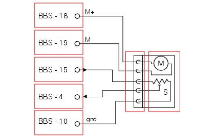
M exhaust bypass valve motor with potentiometer s for position detection, bbs bbs unit connection. 10 Bbs black/blue - bk/b, 15 bbs brown/red - bn/r, 4 bbs yellow/blue - y/b, 18 bbs black/orange - bk/o, 19 bbs black/white - bk/w.
Location of connections and components
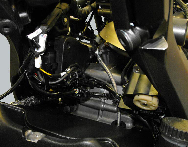
Exhaust bypass valve connection.
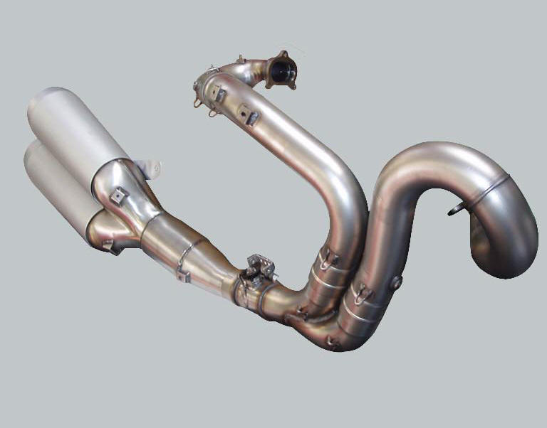
The image shows the exhaust system. The oxygen sensor for the horizontal cylinder (1) is visible on the right, the oxygen sensor for the vertical cylinder (2) is on the left. The catalytic converter is contained within the silencer, while the by-pass valve is installed in the section of pipe connecting the silencer to the twin tailpipes. A metal cable, controlled by an actuator with electric motor and a position sensor, branches off from the exhaust bypass valve.
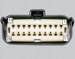
Pin numbering of wiring harness side bbs unit connection
 Stop light not working
Fault codes
Dds: stop light diagnosis -> stop light error (generic stop light malfunction
indication).
Dashboard: the error "stop light" is shown on the service display. The eobd
warning li ...

Other materials:
Refitting the rear sprocket
Check the cush drive bushes (6) condition and, if necessary, replace them by
removing them from the flange.
Refitting is the reverse of removal.
Apply recommended grease on the rear sprocket flange (5) external diameter.
Place the rear sprocket flange (5) on sprocket (17) by inserting it ...
Overhauling the front wheel
Wheel bearings
Before checking the dimensions, check the wear on wheel bearings. Check for
wear by hand after cleaning and degreasing
the bearings in their seats.
Turn the inner race.
Check the amount of radial and axial play. Excessive play will cause vibration
and make the bike unstabl ...
Main bearings
The main bearings have are of the angular contact type with offset inner
races so that the balls transmit loads from one
groove to the other along straight lines at an angle to the axis of the bearing.
The angle-contact ball bearings are
designed for bearing combined loading (radial-axial load ...