
Ducati Diavel Service Manual: Exhaust system
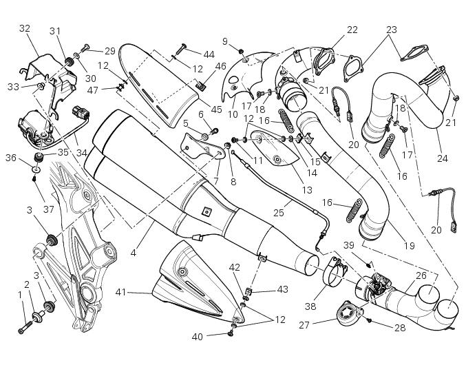
- Screw
- Bush
- Vibration damper mount
- Silencer
- Washer
- Screw
- Bracket
- Nut
- Nut
- Upper heat guard
- Screw
- Washer
- Central heat guard
- Spacer
- Clip nut
- Long exhaust spring
- Plug
- Sealing washer, thickness 1
- Vertical exhaust pipe
- Lambda sensor
- Nut
- Vertical flange
- Exhaust gasket
- Horizontal flange
- Flexible cable
- Central exhaust pipe
- Exhaust protection
- Screw
- Screw
- Washer
- Rubber pad
- Support
- Spacer
- Exhaust valve motor
- Rubber pad
- Washer
- Screw
- Clamp
- Circlip
- Screw
- Lower heat guard
- Spacer
- Quick-release fastener
- Screw
- Upper heat guard
- Rubber mounting
- Spacer
Spare parts catalogue
Diavel abs exhaust system
Diavel carbon abs exhaust system
Important
Bold reference numbers in this section identify parts not shown in the figures alongside the text, but which can be found in the exploded view diagram.
- Removing the silencer
- Removal of the exhaust system
- Refitting the exhaust system
- Refitting the silencer
 Refitting the air filters
Apply universal sealant in the air duct (2) and (6) groove (d).
Fit seal (7) in the groove (d) having care to place it correctly in the relevant
seat so as to avoid abnormal wrinkles.
Pull o ...
 Removing the silencer
Loosen the clamp (38) that retains the silencer (4) to the complete exhaust
system.
While holding the nut (8), loosen the screw (1) and remove the silencer (4)
from the motorcycle.
Loose ...
Other materials:
Specific operating strategies
Idle speed
No electric motor is used for idle speed regulation (bypass is modulated
instead with the throttle valve), as idle speed
control is effected by the ride-by-wire system. Idle speed is maintained by the
control unit when the speed drops below a
specific threshold and when the clutch ...
Refitting the air filters
Apply universal sealant in the air duct (2) and (6) groove (d).
Fit seal (7) in the groove (d) having care to place it correctly in the relevant
seat so as to avoid abnormal wrinkles.
Pull out the filter cartridge (1) from the seat in the airbox.
Position the rh air duct (2).
Start ...
Throttle valve position sensor
Introduction
The throttle valve position sensor (tps) of the diavel is mounted on the
throttle body.
The sensor is integrated into the throttle valve actuator motor, which
turns the spindle of the vertical cylinder throttle
valve directly.
The sensor sends information to the engine con ...