
Ducati Diavel Service Manual: Explanation of the function of the ride-by-wire system
Mechanism
Via metal cables, the throttle grip operates a roller mounted on one end of a spindle located near the horizontal cylinder throttle valve spindle.
The aps sensor, which measures the position of the throttle grip itself, is mounted on the opposite end of this spindle.
A mechanical stop on the roller limits throttle valve travel via a special system of levers.
Normal ride-by-wire system function
The throttle valves rotate through an arc ranging from completely closed (mechanical end-stop) and the aperture set by the throttle valve, which is determined by the ecu from the information received from the aps sensor, and delimited by the stop position on the roller, but without actually reaching the stop position itself.
The stop on the roller does not therefore mechanically delimit the travel of the throttle valves when the throttle grip is completely released (idle speed condition), there is an angle of approximately 5 between the stop on the roller and the mechanical end-stop of the throttle valves. The throttle valves rotate within this angle to automatically regulate idle speed (target idle speed is 1350 rpm with the engine stabilised at operating temperature)
Ride-by-wire system function in the event of a fault
In the event of a fault of any of the components of the ride-by-wire system, whether electrical or mechanical, the ecu cuts off power to the electric motor normally actuating the throttle valves.
A spring gradually closes the throttle valves against the mechanical end-stop.
If the throttle grip is also closed during this stage, the stop on the roller connected to the throttle grip via metal cables, closes the horizontal cylinder throttle valve with a system of levers.
As the horizontal cylinder throttle valve is connected to the vertical cylinder throttle valve by a link rod, this also closes the vertical cylinder throttle valve.
It is impossible for the throttle to remain stuck open as a result of a ride-by-wire system fault.
Warning
Upon ride-by-wire activation through dds, the twistgrip must be completely turned so that the electric actuator can activate the throttles (their movement is not obstacled by the mechanical stop on the pulley which is connected with the twistgrip, through the metallic flexible wires).
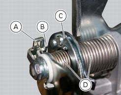
A mechanical stop connected to roller (rotates together with roller), b tang connected to throttle valves (rotates with throttle valves), c roller operated by cables connected to throttle grip, d roller and throttle valve return spring.
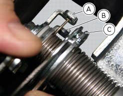
The following is visible in the photo:
- The mechanical stop that rotates together with the pulley;
- The tooth that rotates together with the throttles;
- Pulley operated by cables connected to throttle grip.
In this case (ride-by-wire is working), the mechanical stop (a), driven by the rotation of the twistgrip, is not resting against the tooth (b).
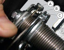
The following is visible in the photo:
- The mechanical stop that rotates together with the pulley;
- The tooth that rotates together with the throttles;
- Pulley operated by cables connected to throttle grip.
In this case (ride-by-wire system malfunctioning), the mechanical stop a, driven by the rotation of the throttle grip as the rider closes the grip itself, is in contact with the tang b, which forces the throttle valves closed.
 Operating principle and characteristics of the ride-by-wire system
The engine control system of the diavel uses a ride-by-wire system with
motorised throttle valves. This eliminates all
direct connection with metal cables between the throttle grip and the throttle ...
 Anti-pollution system and auto-adaptive strategy
Efficacy of the catalytic converter and oxygen sensors
To comply with current emissions legislation, the diavel is equipped with a
trivalent catalytic converter, which oxidises co
(carbon monoxide ...
Other materials:
Refitting the timing covers
Locate vertical cylinder external cover (25), horizontal cylinder external
cover (3) and central external cover (1) by
starting the screws (4).
Apply the recommended threadlocker to the screws (4).
Tighten the screws (4) to a torque of 10 nm (min. 9 Nm - max. 11 Nm) (sect. 3 -
3, Engine t ...
Adjusting the steering head bearings
Note
To adjust the steering bearing clearance, follow what is described in
sect. 4 - 3, Adjusting the steering head bearings.
If the problems found are not solved, check the wear of steering bearings (6)
and replace them, if necessary, as described
in paragraph "removal of the steering head c ...
Overhauling the front forks
Note
It is advisable to loosen the top cap (14) when the fork is still fitted
to the motorcycle.
Note
The specific tools for the revision of the fork, are described in sect. 3
- 4, Specific tools for the frame.
Loosen the spring preload adjuster before unscrewing the plug (14).
Unscrew th ...