
Ducati Diavel Service Manual: Filling the clutch circuit
Warning
Clutch fluid will damage painted surfaces if spilled on them. It is also very harmful if it comes into contact with the skin or with the eyes; in the case of accidental contact, wash the affected area thoroughly with plenty of running water.
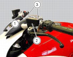
Remove cover (1) and membrane from the clutch fluid reservoir (2) by loosening the screws (3).

Fill the tank with specified oil (sect. 3 - 2, Fuel, lubricants and other fluids) taken from an intact container.
Important
During the following operation, the fluid level must remain topped up at all times. The end of the transparent plastic tubing must remain immersed in the discharged fluid at all times.
Operate the clutch lever and keep it pulled to fill the circuit and expel any air.
Connect the bleed tool to the bleed valve (4).
Note
Follow the manufacturer's instructions when using a commercial clutch bleeding tool.
Loosen the bleed valve (4) and pump with the bleeder. Make sure that the reservoir level does not fall below the min mark.
Repeat the bleeding operation until the fluid flowing from the tube is completely free of air bubbles.
If you do not have a bleeding tool available, connect a length of transparent plastic tubing to the bleed valve (4) as outlined in the draining procedure.
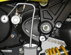
Open the bleed valve by 1/4 turn and operate the clutch lever several times until the fluid flows out of the bleed valve (4).
Pull the lever fully in and then loosen the bleed valve by at least a 1/4 turn.
Wait for a few seconds; then release the lever gradually while simultaneously closing the bleed valve (4).
Important
Do not release the clutch lever until the bleed valve has been fully tightened.
Repeat the bleeding operation until the fluid emerging from the plastic tube is free of air bubbles.
Close to a torque of 4 nm +/- 10% (sect. 3 - 3, Frame torque settings) the bleed valve (4) and install the protection cover.
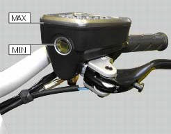
Top up the fluid level to approximately 3 mm above the min mark of the tank.
Reassemble cover (1) and membrane from the clutch fluid reservoir (2) by tightening the screws (3).
 Draining the clutch hydraulic circuit
Warning
Clutch fluid will damage painted surfaces if spilled on them. It is
also very harmful if it comes into contact with the skin or
with the eyes; in the case of accidental contact, wash the a ...
 Adjusting the steering head bearings
Excessive handlebar play or shaking forks in the steering head indicate that
the play in the steering head bearings
requires adjustment. Proceed as follows:
loosen the clamp screw (1) that holds t ...
Other materials:
Abs disabling function
This function disables or enables the abs.
To access the function it is necessary to view the "setting" menu page 48, using
button (1, fig. 14) ?"
" or (2, fig. 14) ?"" select the "abs" function and
press the reset button
(12, fig. 12) To go to next ...
Reassembly of the gearbox shafts
Figure 1 shows all the parts to be reassembled on the gearbox primary shaft
(2), with the calculated end shims (1) and
(11) (sec. 9 - 9.2, Reassembly of the crankcase halves).
Figure 2 shows all the parts to be installed on the gearbox secondary shaft
(25), with calculated end shims (15) a ...
Refitting the rear footrests
Note
The refitting of the rear footrests is described for the right side but it
is the same for both.
If previously removed, refit the rubber footrest (11) on the rear rh footrest
(6), by pushing it until pad (b) engages in the
other side.
Note
The rubber footrest (11) side featuring the le ...