
Ducati Diavel Service Manual: Flexible wiring/hoses positioning
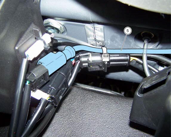
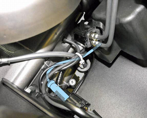
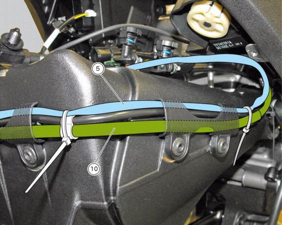
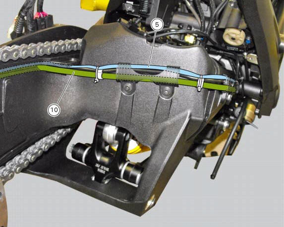
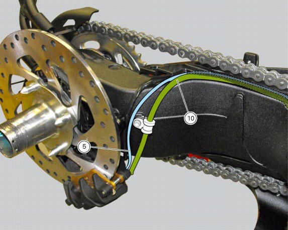
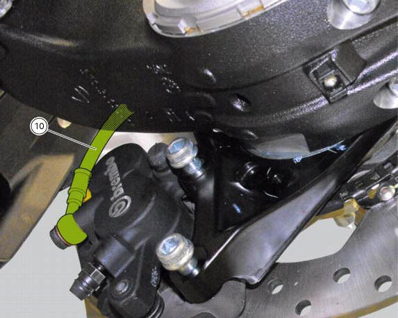
The routing of the abs wiring has been optimised to ensure the minimum obstruction.
Each section is designed to prevent interference with parts that might damage wires or cause operating failures when riding.
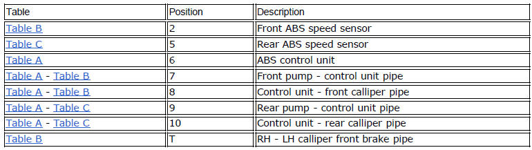
Table a
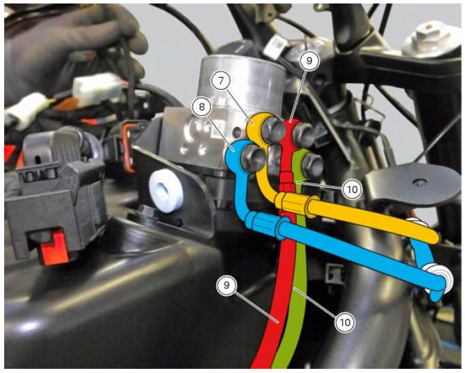
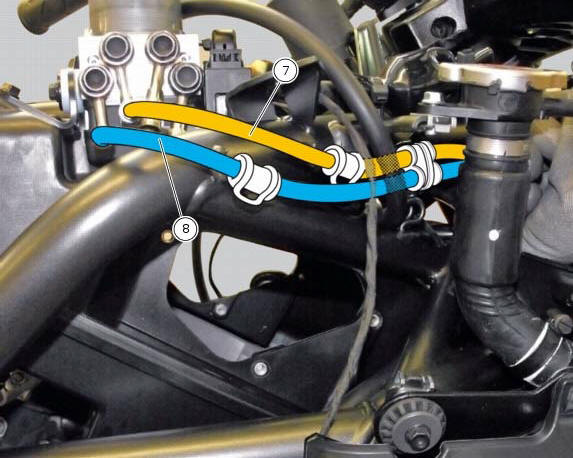
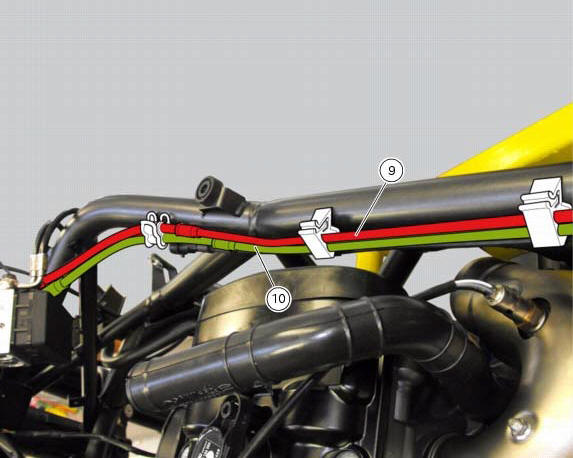
Table b
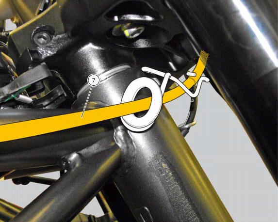
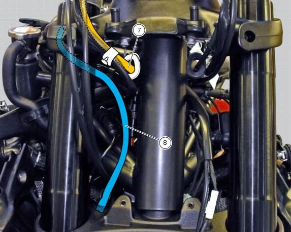
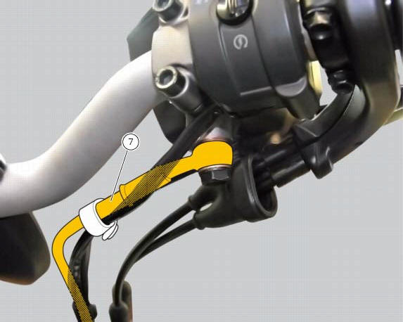
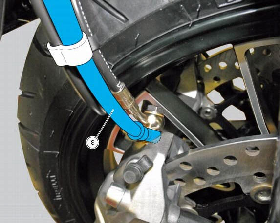
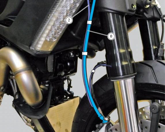
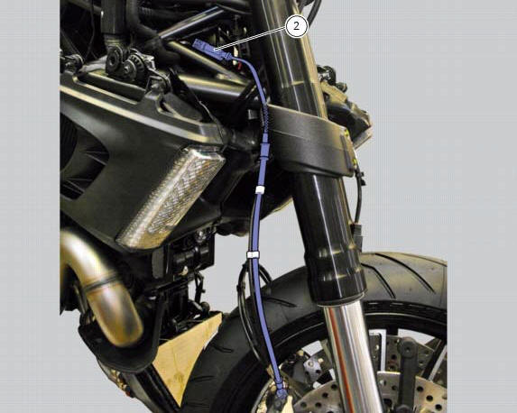
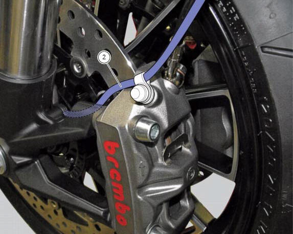
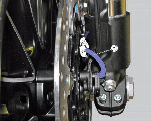
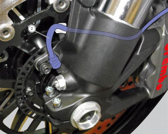
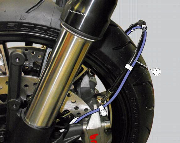
Table c
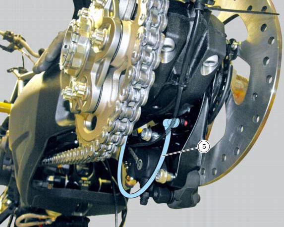
 Refitting the abs control unit
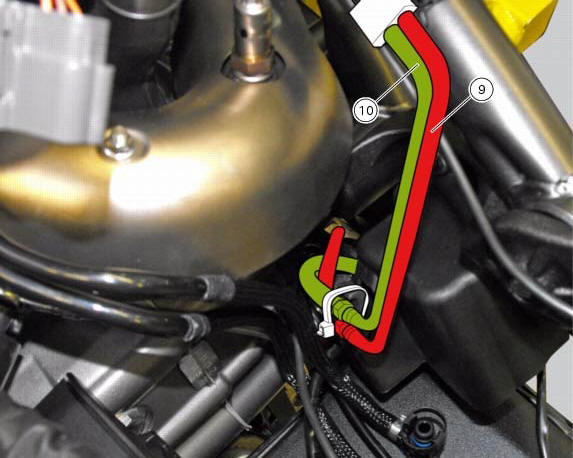
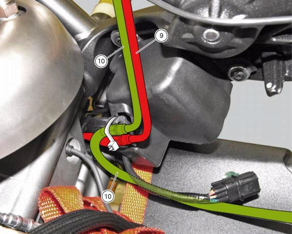
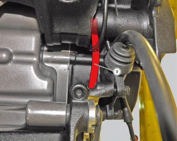
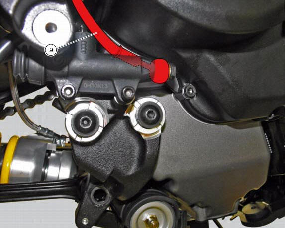
If the brake hoses (7), (8), (9) and (10) on the abs control unit are changed
or removed, ensure that the fittings on the
control unit are positioned correctly.
Warning
If incorrectly positioned, ...

Other materials:
Appropriate diagnosis tools
97900.0211 Dds (ducati diagnosis system) without cables
97900.0227 Power cable and diagnosis
97900.0222 Power cable and diagnosis 1060838 (measurement module)
97900.0218 Vacuum sensor
552.1.039.1A Pressure sensor
97900.0220 Pressure/vacuum tube
97900.0221 Union
...
Operating principle and characteristics of the ride-by-wire system
The engine control system of the diavel uses a ride-by-wire system with
motorised throttle valves. This eliminates all
direct connection with metal cables between the throttle grip and the throttle
valves themselves. Cables are used to
rotate the aps potentiometer, which generates an electric ...
Reassembly of the gearbox shafts
Figure 1 shows all the parts to be reassembled on the gearbox primary shaft
(2), with the calculated end shims (1) and
(11) (sec. 9 - 9.2, Reassembly of the crankcase halves).
Figure 2 shows all the parts to be installed on the gearbox secondary shaft
(25), with calculated end shims (15) a ...