
Ducati Diavel Service Manual: Front brake control
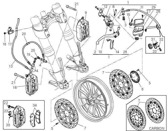
- Front brake master cylinder
- Brake lever
- Special screw
- Sealing washer
- Screw
- Phonic wheel
- Brake disc
- Pin
- Left brake calliper
- Boot
- Bleed valve
- Spare stand
- Control unit - front callipers pipe
- Microswitch
- Oil duct union
- Screw
- Hose clip
- Right brake calliper
- Special screw
- Front brake hose
- Screw
- Dust cap
- Bleed valve
- Front pump - control unit pipe
- Special screw
- Union
- Plug
- Inspection plug (replacement part)
- Fluid reservoir assembly
- Clip
- Hose clip
- Washer
- Screw
- Pair of brake pads
Spare parts catalogue
Diavel abs front brake
Diavel abs front and rear wheels
Diavel carbon abs front brake
Diavel carbon abs front and rear wheels
Important
Bold reference numbers in this section identify parts not shown in the figures alongside the text, but which can be found in the exploded view diagram.
- Removal of the front brake master cylinder
- Refitting the front brake master cylinder
- Maintenance operations
- Removal of the front brake system
- Removal of the brake discs
- Overhauling the front brake components
- Refitting the brake disks
- Refitting the front brake system
 Refitting the rear wheel
Lubricate the wheel shaft threaded end with prescribed grease.
Insert the wheel shaft by matching (a) with pins (b).
Install spacer (3) with the conical surface faced to the wheel conical ...
 Removal of the front brake master cylinder
Warning
The brake master cylinder manufacturer advises against servicing the
brake master cylinder due to the safety critical
nature of this component. Incorrect overhaul of these critical safety ...
Other materials:
Protective apparel
Always wear a helmet. Most motorcycle accident fatalities
are due to head injuries.
For safety eye protection, gloves, and high top, sturdy boots
should also be worn.
The exhaust system becomes very hot during operation,
never touch the exhaust system. Wear clothing that fully
covers your ...
Ignition coils
Introduction
The engine control system of the diavel includes two ignition coils: one for
the horizontal cylinder and one for the vertical
cylinder. These coils are installed directly in the spark plug wells. A diode is
installed on the secondary winding inside the
coil, which prevents the un ...
Inputs and outputs of engine control unit and connection to can network
The diagram illustrates the inputs and outputs for the engine control unit.
The signals from the brake buttons, the exhaust
by-pass valve command signal and the gear sensor signal are transmitted over the
can line.
1I emergency engine cutout switch
2I start button
4I side stand button
6 ...