
Ducati Diavel Service Manual: Fuel pressure test
Note
The on-screen icons used during this procedure are explained in a table at the end of this section.
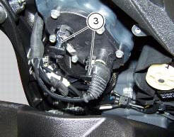
Undo the screws (2) and remove the flange cover (1).
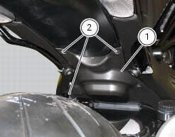
Remove one of the two pipes of the fuel system (3).

Use the fuel pressure pipe (4) part no. 590.1.189.1A by connecting one end (d) to the coupling of the delivery pipe to the tank and the other end (e) to the fuel system pipe (3): in this way you create a pressure pick-up socket (f).

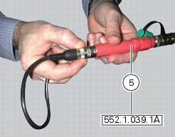
Connect the pressure sensor (5) part no. 552.1.039.1A to the outlet (f) of hose (4), in order to convert the pressure reading into an electric signal.
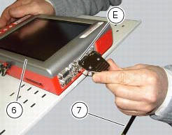
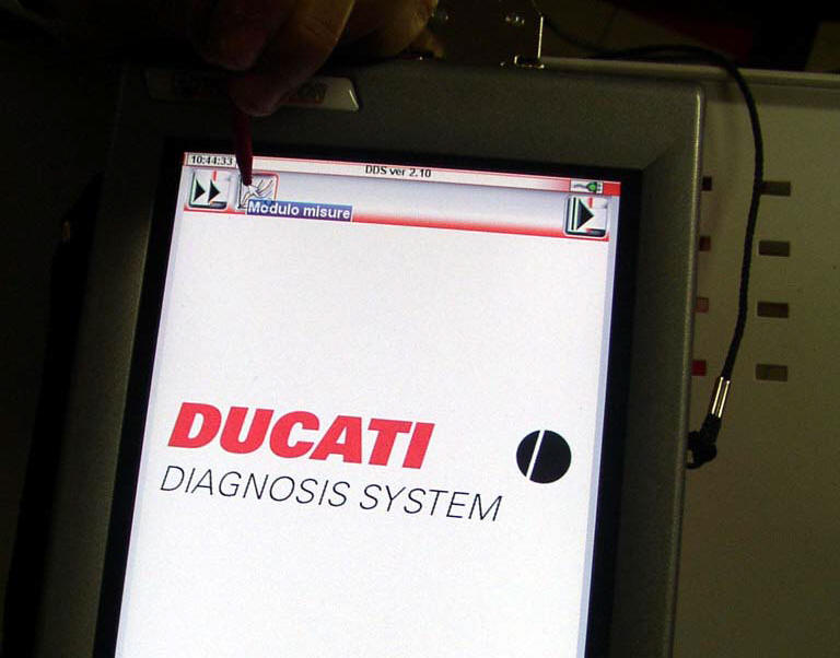
Turn on the dds diagnosis instrument (6) referring to the paragraph "tester power supply".
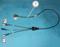
Connect the power and diagnosis cable (measurement module) (7) part no. 97900.0222 To the measurement module connector (e) of the dds (1).
Connect the pressure sensor (6) part no. 552.1.039.1A to outlet (a) or (c) of the cable (7).
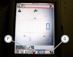
On the dds diagnosis instrument (6), select the "measurement module" function by pressing the corresponding icon; then press the "pressure test" icon (f) followed by the "start" icon (g).
The socket to which the cable (measurement module) (7) is to be connected is indicated on the screen with a capital letter: a, b or c.
The values may be displayed in three different ways: in one numeric form and in two graphic forms; to select the desired display type, press the "value display" icon (h).
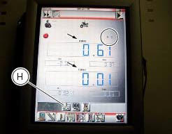
The measured value is indicated alongside the letter (a) or (c) identifying the cable used for the measurement: i.E. If you used socket (a) of the cable (7), the value measured will be displayed next to the letter (a) on the screen.
The maximum pressure must be equal 3 bar (nominal).
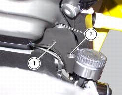
Once the test is over, remove all the components of the test instrument and refit the fuel system pipe (3).
Refit the flange cover (1) by tightening the screws (2) to a torque of 4 nm +/- 10% (sect. 3 - 3, Frame torque settings).


 Cylinder compression test
Note
The on-screen icons used during this procedure are explained in a table at
the end of this section.
Engine performance is directly correlated to the pressure that can be
measured in the com ...
 Guided diagnosis
Note
The on-screen icons used during this procedure are explained in a table at
the end of this section.
The dds diagnosis instrument guides the operator step-by-step through the
various diagnos ...
Other materials:
Refitting the cylinder/piston assembly
If new units are used, it is necessary to couple the cylinders and pistons of
the same selection (see paragraph "overhaul Of the cylinder
barrel/piston components" of this section).
If the pistons have been separated from their cylinders, before reassembling
these components, position the p ...
Display background colour (automatic adjustment)
Instrument panel background colour is set automatically
according to exterior lighting conditions.
When sensor detects "poor lighting" (night), it switches to
black background mode; vice versa when a "significant"
lighting is detected (day), it switches to white background
...
Riding mode customisation
This function customises each riding style.
To access the function it is necessary to view the "setting"
menu page 48, using button (1, fig. 14) ?
or (2, fig. 14)
? select the "riding mode" function
and press the
reset button (12, fig. 12) To go to next page.
W ...