
Ducati Diavel Service Manual: Fuel system circuit
The fuel system circuit consists of:
- An electric pump, driven by the injection relay, which is in turn controlled by the ecu (engine control unit)
- A fuel filter
- A pressure regulator
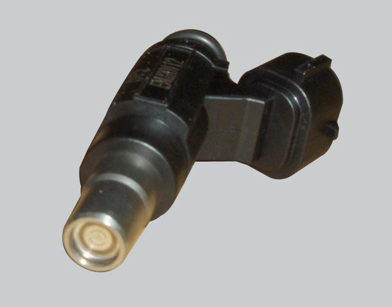
- Two injectors (one per cylinder, located downstream of throttle valve)
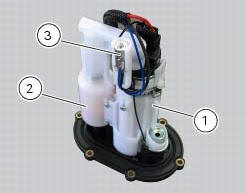
The plastic mounting shown in the figure and mounted in the tank contains the electric fuel pump (centre), the fuel filter (2) and the pressure regulator (3).
The image shows the housing at the bottom of the fuel tank in which the plastic mounting containing the electric pump, fuel filter and pressure regulator is installed.
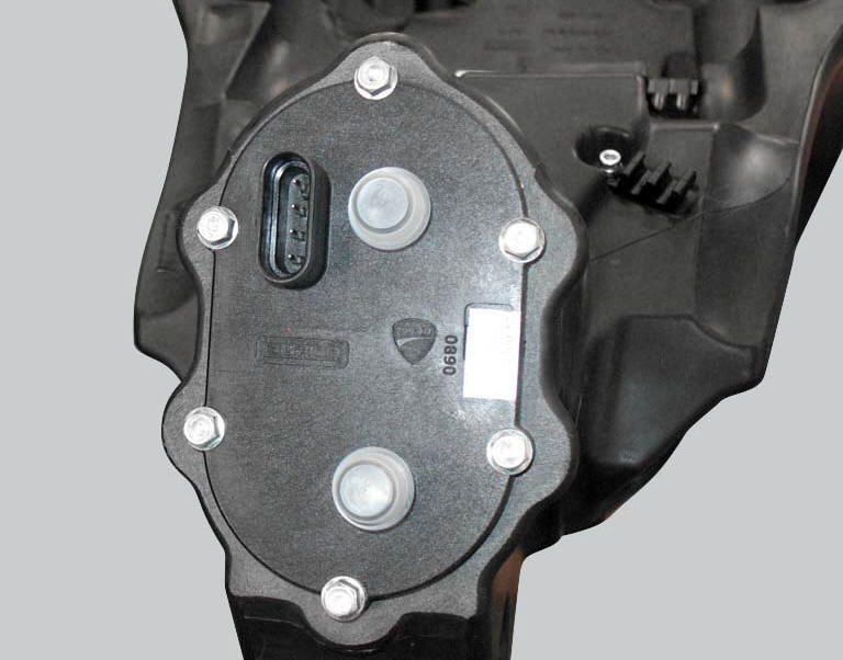
The two pipes of the fuel circuit are connected to the bottom of the tank with quick connectors. The connector (1) on the right is for the fuel delivery line (out), the connector (2) on the left is for the fuel return line (in). Always check carefully that the connectors are fitted correctly and that there are no leaks.
The electric connection for the fuel pump is located under the housing for the plastic mounting for the fuel pump, fuel filter and pressure regulator.
Each cylinder is fed by a single injector with a 12-hole atomiser nozzle. These injectors are installed downstream of the throttle valve.
The drawing shows the layout for the fuel system circuit. The pipes (4) with grey arrows are the delivery lines of the electric pump, which carry fuel to the injectors. The pipe (3) with black arrows is the fuel return line. The fuel return line is connected to the pressure regulator, which is submerged in the tank with the pump and the filter. As a result, the pressure in the fuel delivery and return lines is the same.
- Fuel electric pump
- Fuel filter
- Return line
- Delivery line
- Injectors
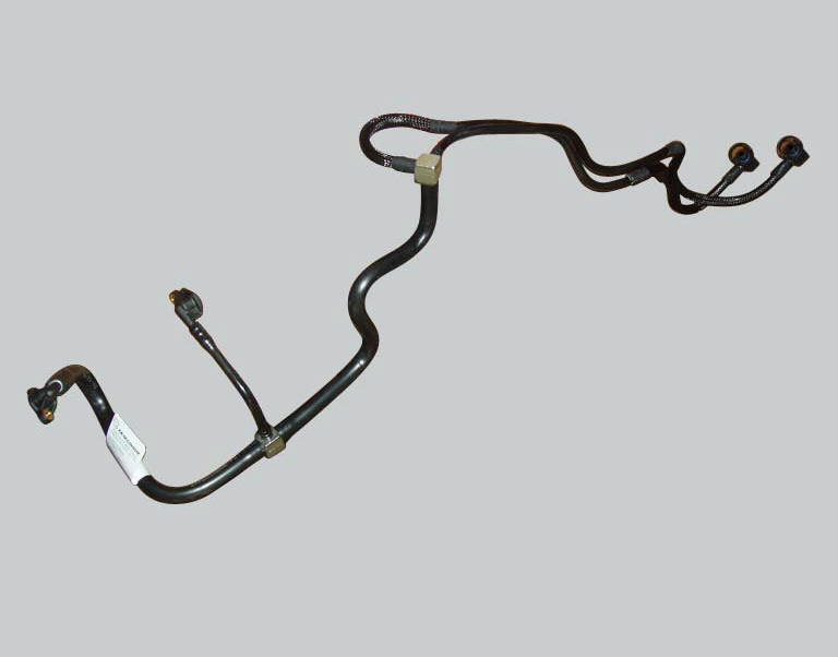
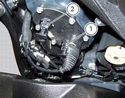
The image shows the pipes in the fuel supply circuit.
Checking regulated fuel pressure and fuel flow rate
The pressure regulator, submerged in the fuel tank together with the pump and the filter, maintains the same pressure of 3 bar in both the delivery and the return lines. This pressure may be checked by connecting a pressure gauge to a t union connected to one of the two connectors on the tank. To measure this value, the engine must be running or the pump activated from the dds. The t union means that the both injectors and the fuel gauge receive fuel pressure simultaneously. The regulated fuel pressure is 3 bar.
To measure the fuel flow rate, disconnect the return line from the tank, place the free end of the line in a graduated container and start the engine or activate the electric pump from the dds.
Warning
When checking fuel pressure and flow rate by activating the pump from the dds, check that the battery is fully charged to ensure correct operation of the pump itself.
An incorrect fuel flow rate and/or pressure may cause engine malfunction, resulting in variation in the self-adaptive parameters defined by the engine control unit. Fuel flow rate and/or pressure values deviating substantially from the rated values will result in an incorrectly generated fuel-air mixture that is too rich or too lean and, as a result, compromise the measurements made by the oxygen sensors. After changing the fuel pump and/or fuel pressure regulator, always reset the self-adaptive parameters with the dds and then use the motorcycle (even by simply running at idle speed) to allow the parameters themselves to recalibrate correctly.
 Reassembly of the control unit
Insert the control unit (4) into the protecting sheath (5) and position it on
the airbox.
Position the relay supporting bracket (2) by starting and tightening the
screws (1) to a torque of 6 ...
 Injection and ignition
Introduction
Ignition is via a single stick coil per cylinder installed in the spark plug
well. Each thermal unit is supplied by a single
injector, placed under the throttle valve. The amount of f ...
Other materials:
Removal of the oil pump
Undo and remove the screws (9) and (10) securing the pump assembly.
Remove the oil pump assembly (1) and extract the o-rings (2) and (4) from the
crankcase half together with two locating
bushes (15).
...
Timing system
Central external cover
Air filter
Horizontal cylinder timing belt cover
Screw
Filter support
Screw
Washer
Nut
Tensioner pulley assembly
Circlip
Camshaft pulley
Tensioner pin
Idler pulley assembly
Timing belt
Nut
Key
Spacer
Camshaft pulley
Driveshaft pulley ...
Refitting the hands free
Reassembly is a reversal of the removal procedure: in particular apply
prescribed threadlocker to screws (2) and tighten
them to a torque of 20 nm +/- 10% (sect. 3 - 3, Frame torque settings).
If the hands free button has been previously removed, when refitting it insert
the spring (6) on pi ...