
Ducati Diavel Service Manual: Gearbox shafts
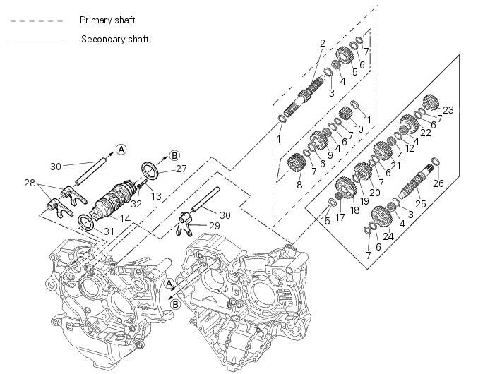
- Shim, thickness 1
- Gearbox primary shaft
- Shim, thickness 0.5
- Needle roller bearing
- 5Th speed driving gear
- Splined washer, thickness 0.5
- Circlip
- 3Rd- 4th speed driving gear
- 6Th speed driving gear
- 2Nd speed driving gear
- Shim, thickness 1.8
- Splined washer, thickness 0.5
- Special needle roller (square cross-section)
- Selector drum
- Shim washer
- Selector drum assembly
- Needle roller bearing
- 1St speed driven gear
- Shim, thickness 1
- 5Th speed driven gear
- 4Th speed driven gear
- 3Rd speed driven gear
- 6Th speed driven gear
- 2Nd speed driven gear
- Gearbox secondary shaft
- Shim washer
- Shim, thickness 1
- 1St, 4th- 2nd, 3rd speed selector fork
- 5Th, 6th speed selector fork
- Selector fork shaft
- Shim, thickness 1
- Needle roller retaining circlip (square cross-section)
Spare parts catalogue
Diavel abs gearchange control
Diavel abs gearbox
Diavel carbon abs gearchange control
Diavel carbon abs gearbox
Important
Bold reference numbers in this section identify parts not shown in the figures alongside the text, but which can be found in the exploded view diagram.
- Removal of the gearbox assembly
- Disassembly of the gearbox shafts
- Overhaul of the gearbox
- Inspection of the gear selector forks
- Inspection of the gear selector drum
- Reassembly of the gearbox shafts
- Reassembly of the gearbox
 Refitting the gear selector lever
Position the gearbox drum selector fork in the centre of the gear rollers.
Position the gear selector lever (21) together with control shaft, spring and
plate into the chain-side crankcase half.
...
 Removal of the gearbox assembly
Withdraw the selector fork shafts (30).
Move the forks (28) and (29) to disengage them from the slots in the selector
drum (14).
Withdraw the selector drum (16) taking care not to lose s ...
Other materials:
Dashboard system
The vehicle is equipped with two dashboards: an lcd (1) located on the
handlebar containing the key indications (speed,
rpm, engine coolant temperature, and clock) and a tft colour display (2) located
in the tank fairing displaying trip
information (riding style set, odometer, consumption, ave ...
Electrical components support
Clip
Screw
Voltage regulator
Battery fixing bracket
Battery support
Vibration damper mount
Hose clip
Vibration damper mount
Clip
Washer
Screw
Cover
Cable grommet
Battery
Battery mat
Screw
Bracket
Solenoid starter
Spring washer
Spacer
Screw
Horn
Scre ...
Changing the clutch fluid
Warning
Clutch fluid will damage painted surfaces if spilled on them. It is
also very harmful if it comes into contact with the skin or
with the eyes; in the event of accidental contact wash the affected area with
abundant running water.
Remove cover (1) and membrane from the clutch fluid res ...