
Ducati Diavel Service Manual: High beam lights not working
Fault codes
The hi beam light on the (slave) dashboard flashes at 1hz frequency.
Wiring diagram
Location of elements on motorcycle
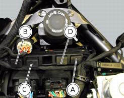
(A) injection relay; (b) etv relay (throttle valve operating engine); (c) radiator fan relay; (d) hands free relay.
Fuses located at the rear left of the vehicle.
(1) 10A dashboard; (2) 5a engine control unit; (3) 15a key-sense; (4) 20a injection relay; (5) 10a throttle opening relay (etv).
Fuses located at the rear right of the vehicle.
(1) 7.5A black box system (bbs); (2) 7.5A navigator/alarm; (3) 25a abs 2; (4) 30a abs 1; (5) 10a fans; (6) 7.5A diagnosis/recharge.
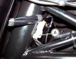
(A) low / high beam and parking light connections
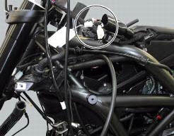
Location of left hand handlebar switchgear set connection.
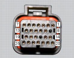
Pin numbering for wiring harness side dashboard connector.
Note
Check integrity of electric circuit - short-circuit to vdc = with dashboard on, using a voltmeter, a voltage is measured between the wire tested and ground.
Check integrity of electric circuit - short-circuit to ground = with the battery cables disconnected, using an ohmmeter, continuity is detected between the wire tested and ground.
Check integrity of electric circuit - open circuit = with the battery cables disconnected, using an ohmmeter, no continuity is detected between the two ends of the wire tested.

 Low beam lights not working
Location of connections and components
(A) injection relay; (b) etv relay (throttle valve operating engine); (c)
radiator fan relay; (d) hands free relay.
Fuses located at the rear left of ...
Other materials:
Rear brake
Rear speed sensor (abs)
Screw
Washer
Spring
Brake switch (rear)
Brake lever (rear)
Rear pump - control unit pipe
Sealing washer
Pin
Bush
O-ring
Screw
screw
Rear brake disc
Rear brake calliper
Rear brake master cylinder
Hose clip
Pushrod
Screw
Rubber pad
...
Removal of the fuel tank
On the usa version remove the canister filter as indicated in sect. 8 - 10,
"Removal of the evaporative emissions
canister".
Loosen and remove the front retaining screw (4)
Remove the flange cover (a) by loosening the screws (b), disconnect the
quick-release fittings (c) from the fl ...
Residual range indication when the service is due
After resetting the first oil service warning (triggered at
1000 km), upon every key-on the system displays the
indication of which type of service should be performed next
(oil service or desmo service) and the residual range.
A (green) warning (1, fig. 32) Is activated for 2 seconds on
ever ...